
MIM Material Properties
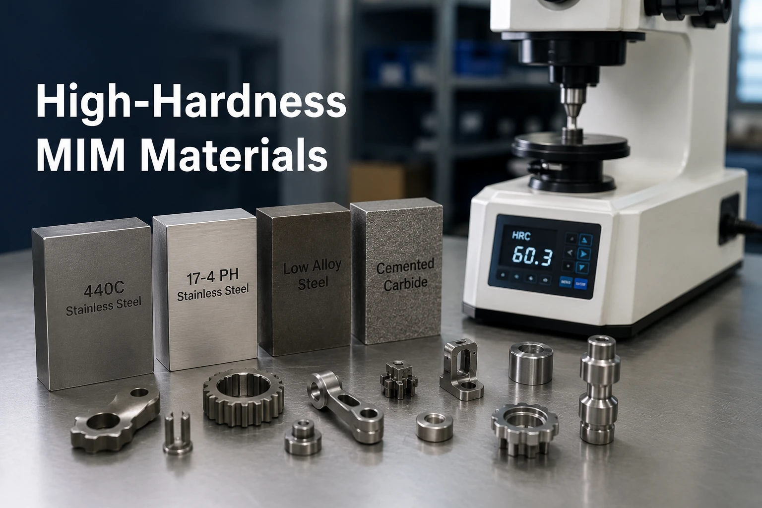
High-hardness MIM materials are used when a small, complex metal part must resist indentation, edge deformation, hard contact, sliding damage, or localized surface wear. The correct choice is not simply the material with the highest hardness value. It must also match the required toughness, corrosion exposure, heat treatment condition, dimensional stability, surface finish and inspection method. Common MIM material directions include 420 stainless steel, 440C stainless steel, 17-4 PH stainless steel, selected heat-treatable low-alloy steels and cemented carbide candidates for severe wear. Engineers and sourcing teams can use these factors to decide whether a high-hardness MIM material is appropriate, when another material path is safer, and what should be confirmed before tooling or RFQ submission.
The practical question is not “which MIM material is hardest?” The better question is whether the selected material can meet the functional hardness requirement without creating unacceptable cracking, heat treatment distortion, inspection difficulty, cost increase, or production risk.
Small hard-contact components, edge-retention features, precision wear surfaces, miniature gears, latch features, valve parts, pump components and compact mechanisms where material selection must be checked together with MIM geometry, sintering shrinkage and final hardness inspection.
When High-Hardness MIM Materials Are Needed
High-hardness MIM materials are usually considered when the part function involves contact stress, surface deformation, edge retention, sliding movement, or localized wear. In practice, this requirement appears in small mechanical mechanisms, locking features, miniature gears, precision hardware, regulated device components, pump components, valve components and compact assemblies where machining a complex geometry from hardened stock may be inefficient.
Important distinction: A hard material is not automatically the strongest or most wear-resistant material for every application. The correct material direction should start from the failure mode: local indentation, sliding wear, abrasive contact, structural load, corrosion exposure, edge chipping, or dimensional instability after heat treatment.
Parts that require resistance to indentation or edge deformation
High-hardness MIM materials may be appropriate when the part has functional edges that must resist rounding, contact surfaces that repeatedly press against another metal part, small gear teeth, ratchet features, latch features, locking surfaces, sliding contact areas, or compact precision geometry that would be expensive to machine after hardening.
These parts still require standard MIM design review for feedstock flow, injection molding feasibility, green-part handling, debinding stability, sintering shrinkage, tooling compensation and final inspection. High hardness does not reduce the need for geometry review; thin walls, small holes, sharp transitions and hard-contact surfaces can become more sensitive to cracking, distortion and finishing risk.
When a high-hardness material may not be the right starting point
A high-hardness material may not be the best first choice when the real requirement is corrosion resistance, elastic load capacity, impact toughness, appearance, low-cost volume production, or a broad tolerance window. For example, 316L stainless steel may be a better starting point when corrosion resistance dominates, 17-4 PH stainless steel may be a better direction when the part needs strength and stainless performance, and a low-alloy steel may be more practical when the part works inside a protected mechanism and corrosion exposure is limited.
When high hardness may be over-specified
High hardness can increase material, heat treatment, finishing and inspection complexity. It may be over-specified when the part is not failing by indentation, edge deformation or hard contact. Before selecting the hardest available material, confirm whether the real requirement is corrosion resistance, structural load capacity, fatigue behavior, smooth assembly, cosmetic finish, low friction, or lower-cost production.
- If corrosion is the dominant issue, start with corrosion-resistant stainless or special alloy review rather than maximum hardness.
- If impact or shock loading is dominant, review toughness and geometry before increasing hardness.
- If the part is mainly load-bearing, review high-strength materials rather than hard-contact materials first.
- If the part has thin unsupported edges, sharp corners, or tight post-treatment dimensions, check heat treatment distortion and cracking risk early.
- If the part only needs moderate surface durability, a balanced material may be safer and more economical than an extreme-hardness option.
On mobile, swipe horizontally to view the full table.
| User requirement | Better material direction | Risk to review before tooling |
|---|---|---|
| Edge retention | 420 stainless steel, 440C stainless steel, or tool-steel-type candidate | Brittleness, edge chipping, stress concentration and heat treatment distortion |
| Wear surface | 440C stainless steel, cemented carbide, or another wear-resistant material direction | Contact pressure, lubrication, surface roughness and mating material |
| Strength and corrosion balance | 17-4 PH stainless steel | Useful engineering balance, but not the highest-hardness stainless route |
| Cost-sensitive structural hardness | 4140, 4340, 4605-type low-alloy steel | Corrosion protection, heat treatment response and dimensional control |
| Extreme hard contact or abrasive wear | Cemented carbide candidate | Cost, brittleness, geometry limits and impact sensitivity |
High-Hardness MIM Material Options
The best high-hardness MIM material depends on whether the part needs stainless corrosion resistance, higher wear resistance, structural strength, impact tolerance, or extreme hardness. Use the material groups below as starting points rather than interchangeable substitutes.

420 stainless steel for hardenable corrosion-resistant parts
420 stainless steel for hardenable MIM parts is often reviewed when a part needs hardenability, moderate corrosion resistance and better hardness potential than austenitic stainless steels such as 304 or 316L. It can be useful for small mechanical components, latch parts, precision hardware and functional surfaces where corrosion exposure exists but extreme corrosion resistance is not the only priority.
440C stainless steel for higher hardness and wear resistance
440C stainless steel for higher-hardness MIM parts is commonly evaluated when the design requires a higher-hardness stainless material direction. It may be considered for small wear components, bearing-like surfaces, valve-related components, contact pins and precision parts where the main requirement is a harder functional surface.
17-4 PH stainless steel when strength and corrosion balance matter
17-4 PH stainless steel for MIM is better understood as a strength-and-corrosion-balance material direction, not as the highest-hardness stainless option. It may be suitable when the part needs precipitation-hardened strength, stainless performance and dimensional reliability.
Low-alloy steels for heat-treated structural hardness
Low-alloy steel MIM materials such as 4140, 4340 and 4605 may be reviewed when the project needs heat-treated structural performance rather than stainless corrosion resistance.
Cemented carbide materials for extreme hardness and wear
Cemented carbide materials for MIM should be considered only when the application requires extreme wear resistance, hard contact performance, or service conditions beyond typical steel-based MIM materials. They are not simple substitutes for 420 or 440C stainless steel. The review must include geometry, impact load, brittleness, edge design, cost, sintering behavior and finishing requirements.
On mobile, swipe horizontally to view the full table.
| Material group | Best-fit need | Main advantage | Main limitation | Detailed material guide |
|---|---|---|---|---|
| 420 stainless steel | Hardenable stainless MIM parts | Hardness plus moderate corrosion balance | Lower wear potential than 440C; final result depends on heat treatment and geometry | 420 stainless steel |
| 440C stainless steel | Higher-hardness stainless parts | Strong hardness and wear-resistance direction | Toughness, distortion and corrosion trade-offs | 440C stainless steel |
| 17-4 PH stainless steel | Strength plus corrosion balance | Good engineering balance for structural parts | Not the highest-hardness route | 17-4 PH stainless steel |
| 4140 / 4340 low-alloy steels | Heat-treated load-bearing parts | Structural strength and hardenability direction | Corrosion protection usually needed | Low-alloy steel materials |
| 4605 low-alloy steel | Cost-sensitive structural MIM parts | Mature structural material direction | Not a premium high-hardness material | 4605 low-alloy steel |
| Cemented carbide | Extreme wear or hard contact | Very high hardness and wear direction | Cost, brittleness and geometry limits | Cemented carbides |
Relative hardness expectation and inspection method
Use this table as a first-pass comparison rather than a datasheet or acceptance specification. Final hardness should be verified against the selected material condition, MIM process route, heat treatment route, drawing requirement and inspection method.
On mobile, swipe horizontally to view the full table.
| Material direction | Relative hardness expectation | Typical inspection direction | Best used when | Review caution |
|---|---|---|---|---|
| 420 stainless steel | Medium-to-high hardenable stainless direction | Rockwell may be suitable if the test area allows; microhardness may be needed for small features | The part needs hardenability with moderate stainless performance | Confirm heat treatment condition, corrosion exposure and edge sensitivity |
| 440C stainless steel | Higher-hardness stainless direction | Rockwell or microhardness depending on part size, section thickness and test surface | The part needs a harder stainless wear or contact surface | Review toughness, distortion, surface finish and corrosion trade-offs |
| 17-4 PH stainless steel | Balanced strength-and-hardness direction after suitable aging condition | Rockwell may be practical on suitable surfaces; define the condition and location | The part needs strength, stainless behavior and controlled heat treatment response | Do not treat it as the highest-hardness stainless choice |
| 4140 / 4340 / selected low-alloy steels | Heat-treatment-dependent structural hardness direction | Rockwell or microhardness depending on geometry and final condition | The part needs protected structural performance and hardenability | Corrosion protection and post-treatment dimensional control may be required |
| 4605-type low-alloy steel | Practical structural material direction, not a premium high-hardness route | Define hardness scale and condition according to the drawing requirement | The part needs a cost-sensitive structural MIM material direction | Do not use it as the default answer for severe wear or extreme hardness |
| Cemented carbide candidate | Extreme hardness and wear-resistance direction | Inspection method should be confirmed by material system, geometry and customer requirement | The part faces severe abrasive wear or hard contact beyond typical steel-based MIM materials | Review brittleness, impact load, edge design, finishing and cost before selection |
Published Condition-Specific Hardness References
The values below include published MIMA project data and one XTMIM 4340 observation from prior MIM and heat-treatment work. They are condition-specific references, not universal material guarantees or drawing acceptance limits. Final hardness depends on the exact grade, density, heat-treatment condition, geometry, section thickness and inspection method. Define the production requirement on the drawing and verify it under the agreed inspection condition.
On mobile, swipe horizontally to view the full table.
| Material / evidence basis | Condition | Hardness | Test scale | Source | Limitation / how to use it |
|---|---|---|---|---|---|
| MIM-420 stainless steel | HIP processed; annealed for secondary operations; then vacuum heat treated and tempered | 40 HRC minimum | HRC | MIMA published 420 component case | Condition-specific production example. Do not use 40 HRC as the default target for every 420 MIM project. |
| MIM-440C stainless steel | Published final MIM support-tab component; detailed heat-treatment parameters are not stated on the case page | >50 HRC | HRC | MIMA published 440C component case | The case confirms a >50 HRC 440C MIM application, but it does not disclose enough process detail to define a heat-treatment specification. |
| MIM-17-4 PH stainless steel | H900 heat treatment | 36–42 HRC | HRC | MIMA published 17-4 PH H900 component case | Use this as an H900 condition reference for strength and hardness balance, not as a basis for treating 17-4 PH as the highest-hardness stainless option. |
| MIM-4605 low-alloy steel | Heat treated | 37–45 HRC | HRC | MIMA published 4605 component case | One published project range. Other 4605 parts can use different heat-treatment conditions and hardness windows. |
| 4340 low-alloy steel — XTMIM engineering experience | Prior 4340 MIM project experience: before heat treatment / after project-specific heat treatment | About 35 HRC before treatment; above 50 HRC after treatment | HRC | XTMIM first-hand MIM and heat-treatment experience; customer part details are confidential | Experience-based project observation, not a universal 4340 guarantee. Exact customer geometry and heat-treatment parameters are not disclosed. |
Use of these values: Treat them as condition-specific references rather than substitute datasheet values. MPIF Standard 35-MIM — 2025 Edition provides the current MIM material-standard reference; the drawing should still define the required grade, condition, minimum properties and applicable inspection requirements.
Hardness, Wear Resistance and Strength Are Not the Same
Hardness, wear resistance and strength must be evaluated separately. Hardness is useful for controlling indentation resistance, but a hard material can still fail by cracking, fatigue, corrosion, galling, adhesive wear, abrasive wear, poor lubrication, poor surface finish, or dimensional instability.

Hardness measures resistance to indentation, not every failure mode
Hardness testing measures resistance to indentation under a defined method, load, indenter and test condition. It is useful for material comparison and quality control, but it does not replace full design validation. A single hardness value does not automatically describe toughness, corrosion resistance, fatigue behavior, surface finish, or wear life.
In MIM, final hardness depends on more than the alloy name. Feedstock preparation, injection molding, debinding, sintering, final density, microstructure, carbon control, heat treatment condition and inspection method can all influence the result.
Wear depends on contact condition, not hardness alone
Wear performance depends on the actual wear mechanism. A high-hardness material may perform well in one contact condition and poorly in another. Important review points include sliding or rolling contact, abrasive particles, dry or lubricated conditions, mating material hardness, surface roughness, contact pressure, edge geometry, temperature and corrosion exposure.
If the main concern is friction, abrasion, mating-surface behavior, or life under repeated sliding contact, the project should also be reviewed through wear-resistant MIM materials for sliding and abrasive wear.
High strength is a different material question
Strength relates to load-bearing capacity, tensile behavior, yield resistance and structural reliability. Hardness relates more closely to resistance against local indentation or surface deformation. A part may need high strength without requiring the highest hardness. Another part may need a hard contact surface without carrying a high structural load.
For structural load capacity, review high-strength MIM materials for load-bearing parts. For hard contact or surface wear, 420, 440C, selected low-alloy steels, or cemented carbide candidates may be more relevant depending on the environment.
How Heat Treatment Affects High-Hardness MIM Parts
Many high-hardness MIM projects depend on heat treatment, but heat treatment should not be treated as a final shortcut after design decisions are already fixed. It affects hardness, strength, toughness, distortion risk, surface condition and inspection planning.
Hardness depends on alloy, sintered density and heat treatment condition
The same material family can produce different results depending on processing and final condition. A drawing that only says “hard material” is not enough; define the material direction, heat treatment condition, hardness scale, target or acceptance range, and the functional surface that must be tested.
Variables that affect final hardness
- Alloy composition and powder/feedstock route
- Debinding and sintering condition
- Final density and microstructure
- Carbon control where relevant
- Heat treatment condition
- Part geometry and section thickness
- Surface finishing after treatment
- Inspection location and hardness scale
What should be reviewed early
- Whether the hardness target is functional or over-specified
- Whether the part can tolerate post-treatment distortion
- Whether a critical surface needs final machining or polishing
- Whether the chosen hardness test suits the part geometry
- Whether the material should be reviewed under a heat-treatable MIM materials and post-sintering treatment path
Heat treatment can improve hardness but may affect dimensions
Heat treatment can create distortion, especially in asymmetric parts, thin sections, long unsupported features, sharp transitions and parts with uneven mass distribution. For MIM parts, this risk combines with normal sintering shrinkage and tooling compensation. The design team should review datum strategy, critical dimensions, heat treatment sequence and whether any final sizing, grinding, polishing, or machining is needed.
Engineering experience — 4340: In prior 4340 MIM project and heat-treatment experience, hardness was observed at about 35 HRC before heat treatment and above 50 HRC after heat treatment. These values are experience-based project observations, not universal guaranteed properties for every 4340 MIM part. Final hardness depends on the specified heat-treatment route, section thickness, geometry, process condition and inspection method, so the drawing should define the required final condition and acceptance range.
Before tooling: When a project requires both high hardness and tight dimensions, confirm that the complete process route can meet the hardness, dimensional, surface and cost requirements—not only that the alloy can be hardened.
Material Selection Table for High-Hardness MIM Components
Start material selection from the part function. Use the table as a screening guide; the final material and condition still require drawing-specific review.
On mobile, swipe horizontally to view the full table.
| Part requirement | Candidate material direction | What to confirm before tooling |
|---|---|---|
| Small gear with sliding contact | 420, 440C, or low-alloy steel | Wear mode, heat treatment, tooth distortion and lubrication |
| Locking latch or mechanical catch | 420, 17-4 PH, or 4140 | Edge wear, impact load and corrosion exposure |
| Hard contact pin or plunger | 440C, 4340, or cemented carbide | Contact pressure, mating material and brittleness |
| Regulated precision device component | 420, 440C, or Co-Cr if applicable | Cleaning requirement, passivation, hardness test method and material compliance requirement |
| Pump or valve wear part | 440C, cemented carbide, or corrosion-resistant alloy | Fluid exposure, wear particles and sealing surface condition |
| Electronics or consumer mechanism | 420, 17-4 PH, or low-alloy steel | Surface finish, corrosion condition and assembly friction |
| Miniature cam or rotating feature | 440C, 4140, or 4340 | Fatigue, surface roughness and heat treatment distortion |
| High-wear abrasive contact part | Cemented carbide candidate | Impact load, edge design, cost and finishing requirement |
Complete the material review before tooling. Once the mold is designed, late material changes can affect shrinkage behavior, dimensional compensation, heat treatment route and trial schedule. For broader material comparison, use the MIM material selection guide or the 420 vs 440C stainless steel comparison.
Design and Process Risks in High-Hardness MIM Parts
High-hardness materials can improve surface performance, but they can also make design weaknesses more visible. Small MIM parts often have thin walls, holes, slots, ribs, undercuts and small functional edges. These features must be reviewed together with the material and heat treatment condition.

Thin edges and sharp corners may become failure points
A hard material can be less tolerant of sharp transitions, thin unsupported edges and local stress concentration. In production, a sharp corner may look acceptable in CAD but become a cracking or chipping risk after sintering, heat treatment, assembly, or service loading.
Sintering shrinkage and heat treatment can change critical dimensions
MIM requires tooling compensation for sintering shrinkage. High-hardness material projects may also require heat treatment after sintering, which can add dimensional change or distortion risk. The tighter the final tolerance, the more important the review of datum structure, sintering support, part orientation and post-treatment inspection.
Surface finish affects wear performance
A hard material with poor surface finish may still fail in sliding contact. Surface roughness, finishing direction, burr control, polishing, passivation, coating, or grinding can affect performance. If two hard surfaces run against each other, poor surface finish may increase friction, noise, wear debris, or galling risk.
Post-machining becomes more difficult after hardening
Machining strategy should be considered early. Some features may be easier to machine before hardening, while other functional surfaces may require finishing after heat treatment. Harder materials can increase tooling cost, grinding requirement, EDM consideration, or polishing complexity.
On mobile, swipe horizontally to view the full table.
| Risk | Common cause | DFM review action |
|---|---|---|
| Cracking | Sharp transitions, thin sections and local stress | Add radius, review wall thickness and check the load path |
| Distortion | Asymmetric geometry, heat treatment and sintering support | Review datum, support strategy and heat treatment sequence |
| Unstable hardness result | Material condition or test location not defined | Specify hardness scale, test location and treatment condition |
| Wear failure | Wrong wear mode assumption | Review mating material, lubrication, surface finish and contact pressure |
| High cost | Over-specified maximum hardness | Confirm the functional requirement instead of selecting the hardest material by default |
| Poor assembly fit | Dimensional change after treatment | Review tolerance stack-up and final inspection plan |
Hardness specified without wear mode review
A small sliding mechanism was given a high hardness target to improve wear life, but the drawing did not define the mating material, lubrication condition, surface roughness or actual wear mode. That left the contact system under-specified even though the hardness requirement looked clear.
The underlying risk was not indentation alone. Contact pressure, the mating surface, lubrication, surface finish and wear debris could all control service life, so increasing hardness by itself could not resolve the wear problem.
The engineering response is to define the wear mechanism before final material selection: mating material, contact condition, lubrication, surface finish and hardness test method should be agreed together. When wear is the main failure mode, material selection should also be checked against the wear-resistant MIM material path.
Heat treatment distortion in a thin hard component
A small hardenable MIM component with thin arms and a locking edge reached the intended hardness direction after heat treatment, but a critical functional dimension became unstable. The material choice was only part of the problem.
Geometry asymmetry, unsupported thin features, sintering shrinkage, heat-treatment response and datum control all contributed to the dimensional risk. Focusing on hardness alone delayed the dimensional discussion until too late in the process.
The engineering response is to connect geometry and process sequence before tooling: review radii, datum strategy, critical functional areas, sintering compensation, support strategy and post-treatment inspection requirements together with the hardness target.
Hardness Testing and Acceptance Checks
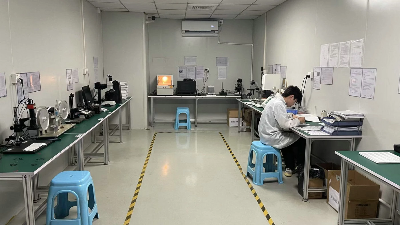
Hardness requirements should be written in a way that can be inspected consistently. A drawing that only says “high hardness” or “hard material” is not sufficient for production or supplier communication. The test method, location and material condition should be defined before tooling or at least before the first article inspection plan is finalized.
Rockwell hardness for metallic MIM parts
Rockwell hardness is commonly used for metallic components when the part geometry and test area allow reliable testing. ASTM E18-25 covers Rockwell hardness testing of metallic materials and includes requirements related to test method, equipment, test-piece thickness and location. A location-specific Rockwell result should not automatically be treated as representative of the whole part. For MIM components, the drawing should identify the acceptance location when local geometry or section thickness could affect the result.
Vickers or Knoop microhardness for small features or thin sections
For small MIM parts, thin sections, surface-treated zones, local hardened regions, or very small test areas, Vickers or Knoop microindentation methods may be more relevant. ASTM E384-22 covers microindentation hardness testing and highlights the importance of test force, specimen preparation and local hardness variation. This matters when a small feature or localized region is being accepted rather than the bulk part.
When Rockwell may not be suitable for small MIM parts
Rockwell testing may be difficult when the available test surface is too small, curved, thin, rough, close to an edge, or affected by local geometry. For miniature MIM parts, local functional areas may require Vickers or Knoop microhardness testing instead of a general Rockwell value. NIST hardness Standard Reference Materials support calibration and verification for Rockwell C as well as Knoop and Vickers microhardness scales, reinforcing why the scale, equipment condition and test method must be specified consistently.
What Should Be Defined on the Drawing?
A useful hardness callout should be inspectable, not just descriptive. Define the items below before final acceptance planning so the supplier and customer are evaluating the same material condition and the same test location.
On mobile, swipe horizontally to view the full table.
| Drawing item | What should be defined | Why it matters |
|---|---|---|
| Material and final condition | Alloy grade plus the required as-sintered, hardened, tempered, aged, or other final condition | The alloy name alone does not define the final hardness. |
| Hardness requirement | Minimum, target, or acceptable range together with the scale, such as HRC, HV, or HK | Prevents ambiguous acceptance criteria. |
| Heat-treatment condition | Required treatment state or approved treatment specification when heat treatment is part of the process | The same alloy can produce different hardness and dimensional results under different conditions. |
| Test method and scale | Rockwell, Vickers, Knoop, or another agreed method that fits the part geometry | Different methods are not interchangeable without an agreed basis. |
| Test location | Functional surface, defined zone, or prepared sample area | A local result may not represent the whole component. |
| Surface / sample condition | As-received, prepared, polished, sectioned, coated, or other relevant state before testing | Surface condition and preparation can affect measurement quality and interpretation. |
| Sampling and acceptance basis | Production part, coupon, prepared sample, inspection frequency, and sampling plan if required | Aligns supplier inspection with the customer's acceptance method. |
| Related functional requirements | Wear, strength, corrosion, surface finish, dimensional or mating-surface requirements that interact with hardness | Prevents hardness from being optimized while the actual failure mode remains unresolved. |
Which Material Property Should Drive the Selection?
High hardness often overlaps with wear resistance, strength, heat-treatment response and corrosion resistance. Start with the property tied most directly to the dominant failure mode. Choose a high-hardness material path for indentation resistance, hard contact or edge retention; use the related guides below when wear, structural load, heat-treatment response or corrosion is the primary requirement.
On mobile, swipe horizontally to view the full table.
| Guide | Primary engineering focus | Use it when |
|---|---|---|
| High-hardness MIM materials | Surface indentation resistance, hard contact and edge retention | You need a hard material candidate |
| Wear-resistant MIM materials | Wear mechanisms and mating-surface behavior | You need to solve friction, abrasion, or sliding wear |
| High-strength MIM materials | Tensile, yield and structural load-bearing performance | You need structural load capacity |
| Heat-treatable MIM materials | Heat treatment response and dimensional risk | You need hardening, aging, or post-sintering treatment review |
| Corrosion-resistant MIM materials | Chemical and environmental resistance | You need corrosion exposure review |
What to Send for Material and DFM Review
If your project requires a high-hardness MIM material, the most useful next step is a drawing-based material and DFM review. This helps confirm whether the hardness target, material direction, geometry, tolerance and process route are aligned before tooling.
Information needed for high-hardness material review
- 2D drawing and 3D CAD file
- Target material or candidate material
- Target hardness and hardness scale
- Required heat treatment condition, if already defined
- Functional wear surface or hard contact area
- Mating material
- Operating load or contact pressure, if known
- Sliding, rolling, impact, or abrasive condition
- Corrosion, fluid, cleaning, or temperature exposure
- Surface finish requirement
- Critical dimensions and tolerance requirements
- Expected annual volume
- Prototype, trial, or production stage
- Application background
What XTMIM engineers should review before tooling
- Material suitability and available feedstock route
- Hardness target realism
- Heat treatment and distortion risk
- Sintering shrinkage and tooling compensation
- Edge, corner, rib, slot and hole risk
- Surface finish and post-processing needs
- Machining, grinding, polishing, or coating requirement
- Inspection method and hardness test location
- Production feasibility, cost drivers and expected volume fit
Request a High-Hardness MIM Material Review
If your MIM part requires high hardness, wear resistance, hard contact performance, or edge retention, send your drawing for a material and DFM review before tooling. Please include 2D drawings, 3D CAD files, target hardness, hardness scale, candidate material, mating material, wear condition, surface finish requirement, critical dimensions, expected annual volume and application background.
XTMIM can review whether 420 stainless steel, 440C stainless steel, 17-4 PH, selected low-alloy steels, cemented carbide materials, or another MIM material direction is more appropriate. The review can also identify risks related to heat treatment distortion, thin edges, sharp corners, sintering shrinkage, surface finish, post-machining and hardness inspection before the project moves into tooling or production planning.
FAQ: High-Hardness MIM Materials
What are the best high-hardness materials for MIM parts?
Common high-hardness MIM material directions include 420 stainless steel, 440C stainless steel, selected heat-treatable low-alloy steels, tool-steel-type candidates, and cemented carbide materials for extreme wear. The best choice depends on hardness target, wear mode, corrosion exposure, toughness requirement, heat treatment condition, geometry, and inspection method.
Which MIM material has the highest hardness?
Cemented carbide candidates are often reviewed when the project requires the highest hardness direction and severe wear resistance, while 440C stainless steel is commonly reviewed for higher-hardness stainless MIM parts. The best choice still depends on geometry, impact load, edge design, corrosion exposure, finishing method and inspection requirements. Do not select a material by maximum hardness alone.
Is 440C harder than 420 stainless steel in MIM applications?
440C is usually reviewed when a stainless MIM part needs a higher hardness and wear-resistance direction than 420. However, the final result depends on the material condition, sintering process, heat treatment, geometry, and acceptance method. 420 may still be a better choice when the project needs a hardenable stainless option with a different balance of cost, corrosion behavior, toughness, or manufacturability.
Does higher hardness always mean better wear resistance?
No. Higher hardness can help resist indentation and some forms of surface deformation, but wear resistance also depends on contact pressure, mating material, lubrication, surface roughness, abrasive particles, corrosion exposure, and motion type. If the main concern is friction or abrasion, the project should be reviewed as a wear system, not only as a hardness requirement.
Can 17-4 PH be used as a high-hardness MIM material?
17-4 PH can be used when the project needs a balance of strength, stainless corrosion behavior, and precipitation-hardening response. It should not be treated as the highest-hardness stainless choice. If surface hardness or wear resistance is the dominant requirement, 420, 440C, or other hard material directions may need to be reviewed.
Can MIM parts be heat treated after sintering?
Some MIM materials can be heat treated after sintering, depending on alloy system and project requirements. Heat treatment may improve hardness or strength, but it can also affect dimensions, distortion, surface condition, cost, and inspection planning. Heat treatment should be reviewed before tooling, especially for thin, asymmetric, or tight-tolerance parts.
Which hardness test is used for MIM parts?
The hardness test method depends on material, part size, section thickness, test surface, and drawing requirement. Rockwell hardness may be used for suitable metallic parts and accessible test areas. Vickers or Knoop microhardness may be more appropriate for small sections, local regions, or thin features. The hardness scale, test location, and condition should be defined clearly on the drawing.
Should small MIM parts use HRC, HV or HK hardness testing?
The hardness scale should match the material, section thickness, test surface, functional area and drawing or customer requirement. HRC can be practical for suitable metallic parts with enough accessible test area. HV or HK may be more appropriate for small features, thin sections, local hardened regions or prepared sample areas. The test method and location should be confirmed before final inspection planning.
What information should I send before selecting a high-hardness MIM material?
Send the 2D drawing, 3D CAD file, target hardness, hardness scale, candidate material, functional wear surface, mating material, operating condition, surface finish requirement, critical dimensions, corrosion exposure, heat treatment requirement, estimated annual volume, and application background. These details help the engineering team review material suitability and DFM risk before tooling.
Standards and Technical References
High-hardness MIM material selection should be guided by recognized material and hardness-testing references, but standards should not replace project-specific engineering review. Specific material property values, hardness targets and acceptance methods should be confirmed against the latest applicable formal standard, material datasheet, drawing requirement, customer specification and actual test results.
- MPIF Standard 35-MIM — 2025 Edition: the current MIM materials standard reference; MIMA states that the 2025 edition supersedes prior editions.
- MPIF Standards: supporting standards and test-method resources for powder metallurgy and MIM material specification.
- ASTM E18-25: current active Rockwell hardness test methods for metallic materials, including requirements related to test method, equipment, thickness and test location.
- ASTM E384-22: current active microindentation hardness test method covering Knoop and Vickers testing for small or localized regions.
- NIST Hardness Standard Reference Materials: calibration and verification reference materials for Rockwell C, Knoop and Vickers hardness scales.