Quick Answer A metal 3D printed design is not automatically moldable by MIM. A printed prototype can validate early shape, assembly fit, or functional direction, but MIM still requires fine metal powder and binder feedstock to fill a mold cavity, release as a fragile green part, survive debinding, shrink predictably during sintering, and meet final …
Quick Answer
A metal 3D printed design is not automatically moldable by MIM. A printed prototype can validate early shape, assembly fit, or functional direction, but MIM still requires fine metal powder and binder feedstock to fill a mold cavity, release as a fragile green part, survive debinding, shrink predictably during sintering, and meet final inspection requirements.
For product engineers and sourcing teams, the key issue is not whether the printed prototype works once. The key issue is whether the geometry can be molded, ejected, debound, sintered, measured, and repeated in production. Internal channels, lattice structures, enclosed cavities, severe undercuts, topology-optimized shapes, or unsupported thin transitions may need redesign before tooling.
This article focuses on MIM moldability review for 3D printed designs. For broader process selection, see the MIM and metal 3D printing process comparison. For a full MIM design framework, use the MIM DFM review guide.

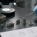
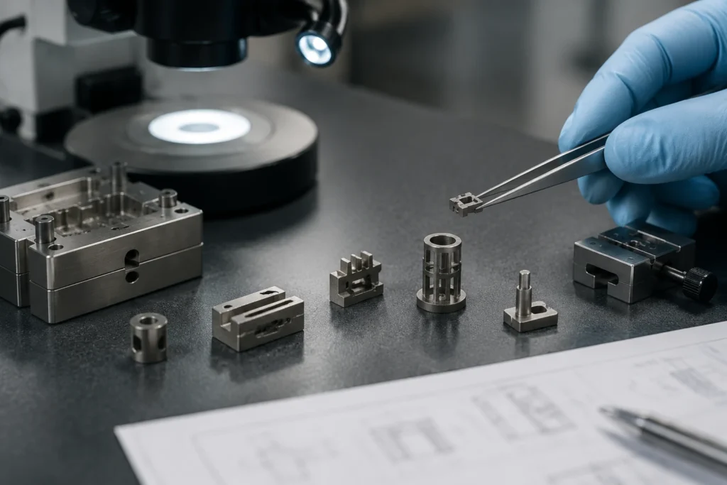
Core conclusion: The workshop image represents the production environment that a redesigned MIM part must eventually fit into. It does not imply that a printed geometry is automatically ready for tooling.
Quick Answer: A Printed Prototype Does Not Automatically Prove MIM Moldability
A printed prototype is useful because it can help a project team test an idea before investing in MIM tooling. It may confirm whether a part fits into an assembly, whether a functional surface is in the right position, whether the product envelope is acceptable, or whether the early concept deserves more development.
What it cannot confirm is whether the same geometry is suitable for a mold-based powder injection process. In practice, a printed part should be treated as a design validation sample, not as final MIM tooling input.
What the prototype can prove
- Basic shape and assembly fit.
- Early functional direction.
- Ergonomic or spatial clearance.
- Local feature concept.
- Early testing before tooling investment.
- Whether a design idea is worth continuing.
What it cannot prove before MIM tooling
- Whether the part has a practical parting line.
- Whether the green part can release without breaking.
- Whether feedstock can fill thin, deep, or isolated features.
- Whether binder can escape during debinding.
- Whether sintering shrinkage can be controlled.
- Whether critical dimensions can be measured repeatedly.
The table below separates prototype validation from MIM pre-tooling review so engineering and sourcing teams do not treat a working printed sample as direct tooling evidence.
| What a Printed Prototype May Validate | What MIM Still Needs to Review |
|---|---|
| Fit and assembly | Parting line and mold release |
| Early function | Green part ejection risk |
| Shape concept | Gate position and filling behavior |
| Local feature performance | Debinding path and section balance |
| Design iteration | Sintering support and shrinkage control |
| User testing | Inspection datum and critical dimensions |
| Prototype material behavior | Production material, density, heat treatment, or finishing route |
A common mistake is treating the printed prototype as the final MIM design. A better workflow is to use the printed part as a physical reference for MIM DFM review before tooling, then modify the geometry only where MIM tooling, debinding, sintering, inspection, or secondary operations require it.
Why Metal 3D Printing Allows Shapes That MIM Cannot Directly Mold
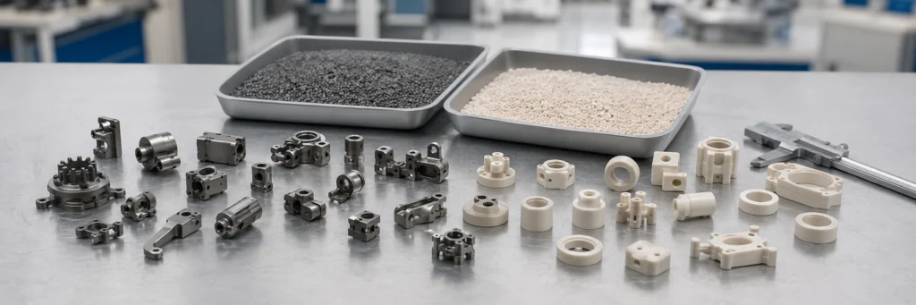
Metal additive manufacturing and MIM can both produce complex metal parts, but their forming logic is different. Metal 3D printing builds geometry from digital data layer by layer. MIM shapes fine metal powder and binder feedstock inside a mold cavity, then removes binder and sinters the part to final metal density.
That difference changes the design rules. The NIST additive manufacturing resource describes AM as a digital, layer-based manufacturing approach. MIM, by contrast, is a mold-based route that must be reviewed through feedstock flow, mold release, debinding, sintering shrinkage and inspection.

Core conclusion: The same CAD shape can face different manufacturing limits depending on whether it is built layer by layer or formed inside a mold cavity.
AM builds geometry layer by layer
Metal 3D printing can create features that do not need a mold opening direction. The build path can form local shapes, internal passages, lattice regions, and organic surfaces that would be difficult or impossible to release from a conventional mold. For prototype development, this can be useful.
However, AM freedom can hide production risks. A part that prints successfully may contain features that have no realistic MIM parting strategy, no stable green-part ejection path, no practical debinding route, or no reliable inspection datum.
MIM forms a fragile green part inside a mold
MIM starts with feedstock, which is a mixture of fine metal powder and binder. During injection molding, this feedstock must fill the mold cavity and form a green part. The green part is not a final metal component. It is fragile compared with the sintered part and must be handled, debound, and sintered before final inspection.
Engineering point: A feature that is printable may still fail during filling, green part ejection, debinding, sintering support, shrinkage compensation, or inspection. This is why a MIM review should follow the complete process route, not only the CAD shape.
The tooling route changes the design rules
For MIM, design freedom is real but not unlimited. The geometry must be reviewed as a molded, debound, sintered, and inspected production part. A printed prototype may help the team understand the product concept, but the MIM version may need adjusted parting surfaces, modified walls, opened cavities, simplified undercuts, added radii, clearer datums, or planned secondary machining.
AM Features That Often Need Redesign Before MIM Tooling
The most important review is not whether the part is complex. MIM can handle many small, complex metal parts. The key question is whether the complexity is moldable, debindable, sinterable, and measurable.

Core conclusion: These features are not automatically impossible for every MIM project, but they should trigger tooling, debinding, sintering and inspection review before cost or mold decisions are made.
AM-to-MIM Moldability Risk Table
The table below maps common AM-friendly geometry to the MIM risk that should be checked before tooling decisions. It also separates redesignable features from features that may justify staying with metal 3D printing.
| AM Design Feature | Why It Prints Well | MIM Risk | Redesign Direction | Keep AM When |
|---|---|---|---|---|
| Internal channels | Layer-by-layer build can form enclosed or curved passages. | Mold core access, binder removal, sintering support and inspection may be difficult. | Open the channel, split the part, simplify the path, or evaluate an assembly design. | The enclosed flow path is essential and cannot be opened, split, cored or inspected. |
| Lattice structures | AM can build internal cellular geometry without a conventional mold release path. | Enclosed lattice networks are usually not practical for standard MIM tooling and debinding. | Replace non-functional lattice with ribs, pockets, holes or wall optimization. | The lattice controls stiffness, weight, energy absorption, flow or other required function. |
| Enclosed cavities | AM can build trapped volumes directly from the digital model. | Core removal, binder escape, trapped contamination and inspection access may fail. | Open the cavity, add access features, redesign the assembly, or move the cavity to a secondary operation. | The cavity must remain fully enclosed and cannot be verified after production. |
| Severe undercuts | AM does not require a mold opening direction. | Mold release and green part ejection may be unstable or impossible without complex tooling. | Reduce the undercut, change the parting strategy, add side action only when justified, or use secondary machining. | The undercut is function-critical and would require excessive tooling complexity for the expected volume. |
| Topology-optimized organic shapes | AM can follow freeform load paths and organic surfaces. | Parting line, gating, support surface, datum definition and inspection may be unclear. | Simplify non-critical surfaces and define measurable datums, functional surfaces and tolerance zones. | The organic geometry itself is functional and cannot be converted into controlled production geometry. |
| Thin isolated ribs or tabs | AM may build local thin features with support strategy. | Feedstock filling, green strength, debinding stress and sintering distortion may become unstable. | Increase support, improve wall transition, adjust orientation, or redesign the feature for molding. | The feature must remain extremely thin, unsupported and dimensionally critical. |
| Unbalanced wall mass | AM may tolerate abrupt section change better during prototype testing. | Debinding and sintering shrinkage may create cracking, distortion or dimensional drift. | Balance wall sections, add transitions, hollow heavy regions where practical, or separate the function. | The mass distribution is fixed by function and cannot tolerate geometry adjustment. |
| AM surface artifacts | Prototype surfaces may be acceptable after support removal or post-processing. | MIM drawing needs controlled surfaces, gate mark strategy, parting line location and inspection criteria. | Define protected surfaces, surface finish requirements, secondary operations and acceptable as-sintered areas. | The AM texture or surface morphology is part of the final product function. |
Internal channels and enclosed cavities
Internal channels are often attractive in metal 3D printing because they can support fluid flow, weight reduction, cooling, or functional integration. In MIM, an enclosed channel may require a core, insert, removable feature, or alternative design strategy. If the internal shape cannot be formed, sealed, debound, or inspected reliably, it is not a direct MIM candidate.
A channel that is open, simple, and aligned with a practical mold direction may be reviewable. A fully enclosed, twisted, branched, or very narrow internal passage is usually a warning sign because tooling access, binder removal and inspection access can all become difficult.
Lattice structures and topology-optimized interiors
AM lattice structures are often used for lightweighting, energy absorption, thermal behavior, or controlled stiffness. MIM usually cannot reproduce enclosed internal lattice networks as a normal molded feature. If the lattice is not functionally required, it may be replaced by ribs, pockets, holes, or wall-thickness optimization. If the lattice is the core function of the part, the design may need to remain in metal 3D printing.
Severe undercuts with no release direction
Some 3D printed features have no concern for mold release. MIM does. An undercut may be possible with slides, side actions, collapsible features, inserts, or post-machining, but every added tooling action increases complexity, maintenance risk, sampling risk and up-front tooling cost. Severe undercuts that trap the green part in the mold may require redesign before MIM tooling.
For a deeper tooling-focused explanation, see MIM mold design review.
Organic shapes without practical parting surfaces
Topology-optimized or organically curved AM parts can be difficult to translate into a stable MIM tool. The issue is not only aesthetics. The part may lack a clean parting line, stable gate area, protected datum, or sintering support surface. If the part must be inspected against a production drawing, the design also needs measurable geometry, not only an optimized surface mesh.
Thin unsupported transitions and wall imbalance
MIM generally favors balanced wall sections and controlled transitions. A printed design with abrupt thick-to-thin sections may work as an AM prototype but cause MIM filling problems, debinding stress, sintering distortion, or dimensional drift. Thin unsupported tabs, long cantilevered features, or heavy mass next to a thin feature should be reviewed before tooling.
For detailed geometry guidance, review MIM wall thickness review.
AM support marks or rough surfaces treated as final geometry
Printed surfaces sometimes include support-removal marks, rough texture, local stair-stepping, or surface irregularity. These should not be blindly transferred into a MIM drawing. A MIM design review should identify which surfaces are functional, cosmetic, protected, machined, polished, coated, or acceptable as-sintered.
The MIMA design guidance on complex MIM features is useful here because it explains how holes, slots, side actions, internally connected features, parting lines and tooling complexity affect MIM design decisions.
Moldable Does Not Always Mean Debindable, Sinterable, or Measurable
Even when a geometry appears moldable, the MIM review should continue through the full process chain. A design that can be injected into a mold may still fail during debinding, distort during sintering, or become difficult to inspect. From a production point of view, mold release is only the first gate.
Debinding path can block some enclosed or thick sections
Debinding removes binder from the molded green part before sintering. A printed design with thick masses, enclosed pockets, or poorly connected internal volumes may create risk during binder removal. The exact risk depends on material system, binder system, section thickness, geometry, debinding method, and supplier process capability.
The practical point is simple: do not evaluate MIM only at the mold cavity level. A geometry that looks moldable must still allow safe binder removal.
Sintering shrinkage can distort unsupported features
MIM parts shrink during sintering. The mold is compensated for expected shrinkage, but the final result still depends on geometry balance, material, furnace support, feature orientation, and inspection requirements. Thin tabs, long arms, asymmetric mass distribution, and unsupported surfaces may move during sintering.
For printed prototypes, this is easy to overlook because the AM part is already metal after the build and post-processing route. The MIM part is not. It becomes final metal only after debinding and sintering. Learn more about dimensional control in MIM shrinkage compensation.
Inspection datums may not match AM organic surfaces
Some metal 3D printed designs are based on organic surfaces or optimized meshes. These can be acceptable for prototype testing, but production inspection requires datums, measurable features, critical dimensions, and acceptance criteria. If the drawing does not define what must be controlled, the MIM supplier cannot reliably evaluate tooling risk, tolerance strategy, or inspection cost.
A MIM-ready drawing should separate functional dimensions from non-critical surfaces. It should also identify protected surfaces, mating areas, thread features, sealing regions, cosmetic surfaces, and any secondary operation needs.
How Engineers Should Review a 3D Printed Prototype Before MIM Tooling
A practical MIM review starts with the printed part, but it should not end there. The design team should review the 3D CAD model, 2D drawing, target material, tolerance needs, surface requirements, application conditions, and expected production volume. Without these inputs, the review easily becomes a rough opinion rather than a tooling decision.

Core conclusion: A sample photo alone is not enough for MIM review. The engineering team also needs the CAD model, drawing tolerances, critical dimensions, protected surfaces and production assumptions.
Check whether the part has a practical parting line
The parting line affects mold construction, witness marks, flash control, feature orientation, and cosmetic surfaces. If a printed part has no obvious parting strategy, the MIM version may require design simplification, hidden parting placement, side actions, inserts, or secondary machining.
Check whether green part ejection is realistic
The green part must release from the mold without breaking. Thin ribs, hooks, delicate tabs, long undercuts, and sharp local features can be risky before sintering. A design that is strong as a printed metal prototype may still be fragile as a green MIM part.
Check whether feedstock can fill thin or deep features
MIM feedstock must flow through the mold cavity before solidifying. Very thin, deep, isolated, or long-flow features can create short-shot risk, weak green areas, weld-line sensitivity, or dimensional instability. Gate location and flow direction matter.
Check whether binder can escape during debinding
Thick or enclosed sections may require additional review because binder removal is part of the process. The design team should check whether the geometry creates trapped sections, heavy masses, or transitions that may increase defect risk during debinding and sintering.
Check whether the part can be supported during sintering
Sintering support is often necessary for features that may sag, warp, or distort. A printed prototype may not reveal this issue because its geometry is not shrinking through a high-temperature sintering cycle in the same way as a MIM part.
Check whether critical dimensions can be inspected after shrinkage
The production drawing should define critical dimensions, datums, tolerance class expectations, surface requirements, and inspection methods. If the AM model only contains freeform mesh data without clear datum control, it should be converted into a production drawing before MIM review.
This checklist summarizes the engineering review points that should be answered before a printed prototype becomes a MIM tooling discussion.
| Review Question | Why It Matters for MIM |
|---|---|
| Is there a practical parting line? | Without it, mold release and flash control may be unstable. |
| Can the green part be ejected safely? | Fragile green features may break before debinding. |
| Can the feedstock fill the feature? | Thin, deep, or isolated features may cause short shot or weak green sections. |
| Can binder escape during debinding? | Thick or enclosed sections may increase defect risk. |
| Can the part be supported during sintering? | Unsupported features may distort during shrinkage. |
| Are datums and critical dimensions clear? | Inspection must be based on measurable production geometry, not only AM surface shape. |
| Are functional surfaces clearly marked? | Gate marks, parting lines, finishing, and machining must avoid protected areas. |
| Is the expected volume clear? | Tooling complexity must be justified by production demand. |
If your team needs a structured pre-tooling review, use the MIM DFM design checklist to organize geometry, material, tolerance and application inputs.
Composite Field Scenario for Engineering Training: Internal Channel Prototype
What problem occurred
A metal 3D printed prototype passed early fit and handling tests. The part included a curved internal channel that helped route fluid through a compact assembly. The project team wanted to evaluate whether the same design could be moved into MIM for repeat production.
Why it happened
The printed channel was possible because the AM build process formed the geometry layer by layer. The channel did not need a removable mold core, direct pull direction, or conventional tool access.
What the real system cause was
The issue was not the part envelope or material category. The real system cause was that the internal channel had no practical MIM forming route. It also raised concerns about binder removal, sintering distortion around the enclosed region, and inspection access after production.
How it was corrected
The design was separated into two review options. One option kept the part in metal 3D printing because the internal channel was essential. The second option redesigned the geometry as an open channel with a cover or assembly feature, allowing the team to evaluate whether a MIM route might be possible after redesign.
How to prevent recurrence
Before using a printed prototype as a MIM reference, mark all internal channels, enclosed spaces, lattice regions, and flow paths on the drawing. Ask whether each feature is functionally required or only a prototype convenience. AM-only features should be identified before tooling cost is estimated.
When the Design Should Stay in Metal 3D Printing Instead of Moving to MIM
Not every metal 3D printed part should be redesigned for MIM. A credible MIM review should also explain when MIM is not the right route. This protects the project from forcing a mold-based process onto a geometry that depends on AM-specific freedom.
The function depends on internal channels
If the part requires enclosed cooling passages, fluid channels, gas paths, or curved internal routes that cannot be opened, split, cored, or inspected, metal 3D printing may remain the better route.
The lattice or porous structure is functional
If the lattice controls stiffness, weight, energy absorption, or flow behavior, replacing it with ribs or pockets may change the function. In that case, forcing the design into MIM can create a product risk, not only a manufacturing change.
The design is still changing
MIM tooling is usually more appropriate after the design is close to frozen. If the team expects frequent geometry changes, metal 3D printing, CNC machining, or another prototype route may be more practical until the design stabilizes.
The volume cannot justify tooling
MIM requires tooling investment and process development. If the expected quantity is low, uncertain, or highly customized, the economics may not justify mold development even if the geometry can be redesigned.
Customization is more important than repeatability
If every order requires a different geometry, serial number, custom interface, or low-volume variation, metal 3D printing may remain more suitable than a fixed mold route. For process selection, see how to choose between MIM and metal 3D printing.
When Redesigning the Printed Part for MIM May Be Worth Reviewing
A printed part may be worth reviewing for MIM when the design has moved beyond concept testing and the project needs repeatable production. The goal is not to copy the printed geometry exactly. The goal is to preserve the required function while adapting the part to a moldable, debindable, sinterable, and inspectable design.

Core conclusion: A MIM feasibility review should consider geometry, drawing readiness, expected volume, protected surfaces, secondary operations and inspection requirements before tooling cost is treated as reliable.
The external geometry is complex but moldable
MIM can be strong for small, complex metal parts when the complexity is mostly external or can be formed with practical tooling. Bosses, ribs, cross holes, slots, small features, textured areas, logos, and thin-wall regions may be reviewable if they support mold release, debinding, and sintering.
The annual volume is becoming predictable
A printed part becomes a stronger MIM candidate when repeat demand is expected and the design is stable enough for tooling. The review should consider not only part price but also tooling cost, redesign cost, sampling risk, inspection needs, secondary operations, and production repeatability.
The AM unit cost is too high for repeat production
If the AM prototype works but repeat production cost, lead time, or post-processing effort is too high, MIM review may be worthwhile. This does not mean MIM is automatically better. It means the project has moved into a stage where tooling-based production should be evaluated.
The function does not require AM-only internal structures
If AM-only structures are not essential, the part may be redesigned for MIM. For example, a non-functional lattice used for lightweighting may be replaced by ribs, pockets, or wall optimization. A purely organic surface may be simplified into controlled production geometry.
The design is close to frozen
MIM review is most useful when the design team can define target material, critical dimensions, protected surfaces, tolerance needs, application requirements, and estimated annual volume. If these inputs are still unclear, the first step should be engineering clarification, not tooling.
The table below helps separate projects that should usually stay in AM from projects that may justify a MIM moldability review.
| Project Condition | Usually Stay in AM | Worth MIM Review |
|---|---|---|
| Design stage | Still changing | Close to frozen |
| Geometry | Internal channels or lattice are essential | External complexity is dominant |
| Volume | Low or custom | Repeat demand is predictable |
| Tooling | Not justified | Tooling can be amortized |
| Cost pressure | Prototype cost acceptable | AM repeat cost is too high |
| Inspection | Organic surfaces only | Defined datums and critical dimensions |
| Material | AM-specific material route required | MIM material option is available or reviewable |
Composite Field Scenario for Engineering Training: Undercut Prototype With No Release Direction
What problem occurred
A small metal bracket was printed and assembled successfully. The prototype had a hook-shaped undercut and a curved retaining pocket that worked well in testing. The buyer wanted to evaluate MIM for repeat production.
Why it happened
The printed design was optimized for function and compactness, not for mold opening, green part ejection, or parting line control. The AM route allowed the undercut to exist without considering mold release.
What the real system cause was
The real system cause was missing MIM tooling logic during prototype design. The undercut trapped the geometry from a simple mold opening direction, and adding side actions would increase tooling complexity. The retaining pocket also created a fragile green feature that could break during ejection.
How it was corrected
The design was modified with a cleaner parting strategy, a less severe undercut, and a secondary machining option for one protected surface. The project team also marked critical dimensions and non-critical surfaces separately so the MIM version did not need to copy every printed surface detail.
How to prevent recurrence
When using AM for early validation, review parting line, ejection direction, gate-sensitive surfaces, and critical features before freezing the design. A printed prototype should include a manufacturing review step before it becomes the basis for MIM tooling.
What to Send for a MIM Moldability Review
For a useful MIM moldability review, the supplier needs more than a screenshot of a printed part. The goal is to understand function, geometry, material, tolerance, production volume, and risk before tooling.
2D drawing and 3D CAD
Send the latest 2D drawing and 3D CAD file. The drawing should identify critical dimensions, datum structure, tolerance requirements, surface finish, threaded features, protected surfaces, and any areas that cannot accept gate marks, parting lines, or finishing variation.
Current printed prototype information
Share the current AM process if known, prototype photos, surface condition, post-processing steps, and which prototype tests have been completed. If the printed part has functional features that are not obvious from the drawing, mark them clearly.
Material and property target
Do not assume the AM material and MIM material will behave identically. Send the required material family, strength expectations, corrosion needs, magnetic behavior, heat treatment needs, coating or plating requirements, and application environment.
Critical dimensions and protected surfaces
Identify the features that control function. This helps the engineering team review shrinkage compensation, tooling risk, inspection method, and whether secondary machining is required.
Surface finish and secondary operation needs
If the part requires polishing, passivation, coating, plating, PVD, laser marking, thread tapping, machining, or heat treatment, these requirements should be reviewed before tooling. Secondary operations can affect cost, tolerance strategy, masking, appearance, and delivery planning.
Estimated annual volume and application background
MIM suitability depends partly on repeat production demand. Estimated annual volume, target launch timing, assembly use, functional load, environment, and quality expectations help determine whether MIM tooling review is reasonable.
The following input list helps the engineering team evaluate moldability, process risk and commercial feasibility before tooling cost is treated as reliable.
| Information to Send | Why It Matters |
|---|---|
| 2D drawing | Defines dimensions, tolerances, datums, and protected features |
| 3D CAD file | Allows geometry and moldability review |
| Printed prototype photos | Shows current AM surfaces, supports, and feature intent |
| Target material | Guides MIM material and heat treatment review |
| Critical dimensions | Supports shrinkage and inspection planning |
| Surface requirements | Helps evaluate finishing and secondary operations |
| Estimated annual volume | Determines whether tooling review is commercially reasonable |
| Application background | Helps identify function, risk, and acceptance requirements |
Need to Review a Printed Prototype for MIM Production?
If your metal 3D printed prototype may move toward MIM production, send the 2D drawing, 3D CAD file, material requirements, tolerance requirements, surface finish needs, estimated annual volume, application background, and a short note explaining which AM features are function-critical.
XTMIM can review whether the geometry has a practical parting line, whether internal features or undercuts create tooling risk, whether the part may face debinding or sintering distortion, whether critical dimensions are measurable, and whether redesign, secondary machining, or another manufacturing route should be considered before tooling.
FAQ: 3D Printed Prototype to MIM Moldability
Can a metal 3D printed prototype be used directly for MIM tooling?
Sometimes it can be redesigned for MIM, but it should not be assumed that the same geometry can move directly into tooling. MIM requires moldability, green part ejection, debinding, sintering shrinkage, and inspection review. A printed prototype may validate function, but it does not automatically validate MIM production feasibility.
Which 3D printed features are usually difficult to mold by MIM?
Internal channels, enclosed cavities, lattice structures, severe undercuts, topology-optimized organic surfaces, isolated thin ribs, and unsupported transitions often need redesign before MIM tooling. Some features may be possible with side actions, inserts, split-part design, or secondary machining, but they must be reviewed case by case.
Does passing functional testing mean the design is ready for MIM tooling?
No. Functional testing only shows that the prototype can perform under the test condition. It does not prove that the geometry can be molded, debound, sintered, measured, and repeated in production. A separate MIM DFM review is still needed.
Can internal channels be made by MIM?
Some open, simple, or well-oriented channel-like features may be reviewed for MIM. Fully enclosed, curved, branched, or very narrow internal channels are much more difficult and may not be suitable for ordinary MIM tooling. The decision depends on geometry, core strategy, debinding path, inspection access, and function.
Should I redesign the part before asking for a MIM quote?
It is usually better to request a moldability review before treating the quote as final. The supplier should review parting line, undercuts, wall balance, green part handling, debinding path, sintering support, critical dimensions, surface requirements, and expected volume before tooling cost and production feasibility are considered reliable.
Should I redesign the part for MIM or keep using metal 3D printing?
If the part depends on internal channels, lattices, low-volume customization, or frequent design changes, metal 3D printing may remain better. If the part is small, externally complex, design-stable, and expected to move into repeat production, MIM redesign may be worth reviewing.
What files are needed for MIM moldability review?
Send 2D drawings, 3D CAD files, target material, critical dimensions, tolerance requirements, surface finish needs, current prototype information, application background, and estimated annual volume. These inputs help the engineering team review tooling risk, shrinkage, inspection, and production feasibility.
Can the same material be used in AM and MIM?
Not always. Similar alloy names do not guarantee identical process behavior, density, surface condition, heat treatment response, or final property profile. Material selection should be reviewed based on the MIM feedstock route, sintering process, application requirements, and inspection needs.
Engineering Review Note
Reviewed by XTMIM Engineering Team from a MIM manufacturability and pre-tooling review perspective.
This article focuses on process suitability, MIM DFM, tooling risk, green part handling, debinding feasibility, sintering shrinkage, tolerance strategy, inspection requirements, surface finishing considerations and production feasibility for metal 3D printed designs being considered for MIM production.
Final manufacturability depends on the actual drawing, CAD model, material requirements, feature geometry, tolerance needs, surface finish, application conditions, expected production volume and inspection plan. Project-specific review is recommended before tooling decisions.
Technical References and Standards Note
This article uses a limited number of references because the decision is geometry- and project-specific. The following resources are useful for understanding the boundary between AM design freedom and MIM tooling review:
- NIST Additive Manufacturing — useful for understanding additive manufacturing as a digital, layer-based manufacturing route.
- MIMA Complex Designs with MIM — useful for understanding holes, slots, parting lines, side actions, internally connected holes and tooling complexity in MIM design.
- MIMA Publications / MPIF Standard 35-MIM — useful as a MIM material specification reference direction. Final material acceptance should be based on the project drawing, material data sheet, supplier agreement and applicable formal standard documents.