MIM Process Selection Insights Quick Answer: When Does a Stamped Assembly Deserve a One-Piece MIM Review? A stamped assembly deserves a MIM review when the finished component is controlled more by joining, secondary operations, assembly variation, and final inspection than by the stamped pieces themselves. The real trigger is often the work around those pieces: …
MIM Process Selection Insights
Quick Answer: When Does a Stamped Assembly Deserve a One-Piece MIM Review?
A stamped assembly deserves a MIM review when the finished component is controlled more by joining, secondary operations, assembly variation, and final inspection than by the stamped pieces themselves. The real trigger is often the work around those pieces: welding, riveting, staking, deburring, reaming, tapping, secondary machining, manual assembly, alignment control, or repeated final inspection.
Metal injection molding is not automatically better than stamping. Simple flat sheet-metal parts, large thin components, and very low-volume projects often remain better suited to stamping. MIM becomes a practical review option when several small stamped pieces create one compact three-dimensional function and the project team needs to compare the finished component route, not only the stamped blank unit price.
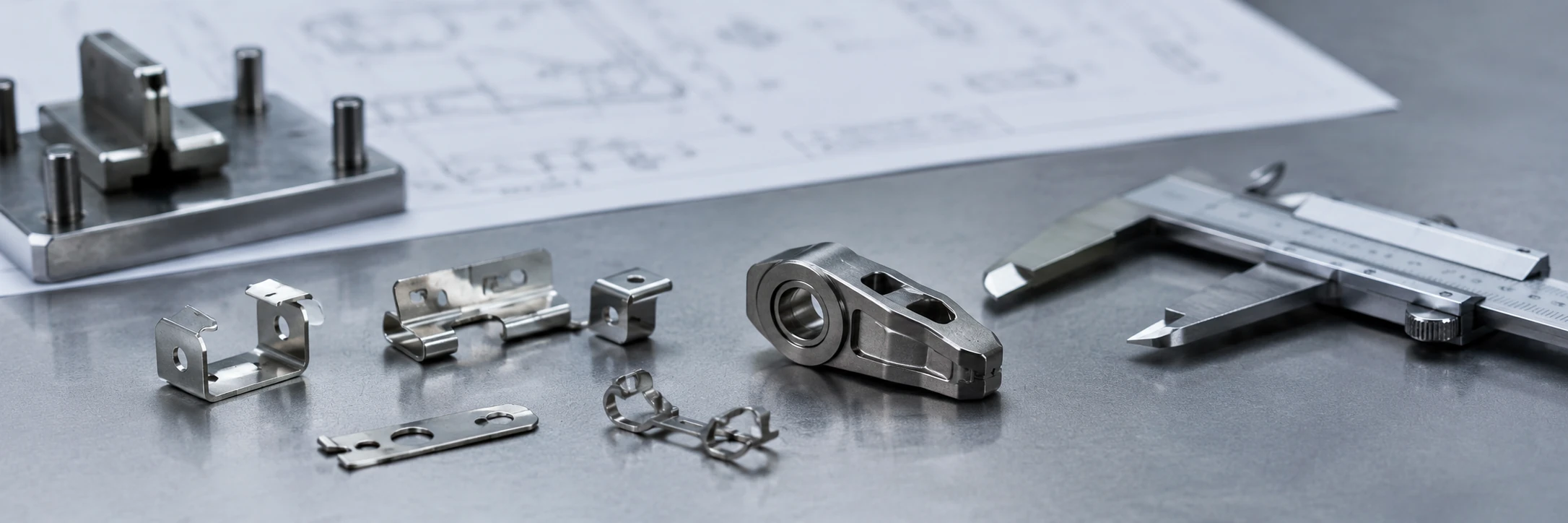
Core conclusion: One-piece MIM is worth reviewing when the final assembly burden becomes more important than the cost of individual stamped pieces.
When Should a Stamped Assembly Be Reviewed as a One-Piece MIM Component?
A stamped assembly should be reviewed for MIM when the part has moved beyond simple sheet-metal logic. In early designs, stamping may be selected because each flat or formed piece is economical, fast to produce, and familiar to the supply chain. The problem appears later when the finished component needs multiple joined parts, tight positional relationships, extra machining, or final assembly inspection to work reliably.
From an engineering review perspective, the question is not, “Can this stamped part be copied by MIM?” The better question is, “Can the final function of this assembly be redesigned as one compact molded-metal component without creating new tooling, shrinkage, inspection, or finishing risks?”
For a broader process comparison, refer to MIM vs stamping process selection. This article focuses only on one narrower question: when a multi-piece stamped assembly should be reviewed as a possible one-piece MIM component.
Assembly work is increasing
Welding, riveting, staking, fastening, or manual alignment may become more important than the stamped blank itself.
Final inspection drives risk
Individual stamped pieces may pass inspection, while the final assembly still fails alignment, position, or functional checks.
Finished cost is unclear
The fair comparison should include joining, finishing, inspection, scrap, rework, and annual volume—not only stamped blank price.
| Review Question | Usually Keep Stamping | Review One-Piece MIM |
|---|---|---|
| Is the part mostly flat sheet geometry? | Yes, simple blank or simple bend. | No, compact 3D function is needed. |
| Is final quality controlled by joining? | No, individual stamped pieces meet function. | Yes, joining alignment affects function. |
| Are secondary operations routine? | No, only light edge control or finishing. | Yes, reaming, tapping, deburring, or machining is repeated. |
| Is annual volume enough for tooling review? | Low volume or uncertain production life. | Stable production volume and assembly burden justify review. |
| Can features be redesigned, not copied? | No, design must remain sheet-like. | Yes, bosses, ribs, lugs, or datum features can be integrated. |
Engineering boundary: This review does not guarantee that MIM will be lower cost or higher precision. It only determines whether the current stamped assembly has enough integration value, finished-route burden, and production volume to justify a MIM DFM discussion before tooling.
Common Assembly Problems That Trigger a MIM Integration Review
The most useful trigger is not the word “stamping” on the drawing. The useful trigger is the amount of work required after stamping. A MIM review becomes more relevant when the current route depends on joining, alignment, correction, and repeated inspection to create the final function.

Core conclusion: Assembly burden is often the trigger for reviewing whether a one-piece MIM component is technically reasonable.
Welded or riveted joints become the quality bottleneck
Welding, riveting, and staking can be practical joining methods, but they also introduce variation. Joint position, heat distortion, fixture repeatability, and local deformation may affect the final geometry. If the assembly requires repeated checks to confirm that joined features remain aligned, the project team should ask whether those features can be integrated into one molded-metal geometry.
This does not mean MIM can remove every joint. It means the joint is no longer only a manufacturing detail. It has become part of the quality risk.
Manual assembly creates variation between batches
When a stamped assembly depends on manual alignment, fixture loading, or operator-controlled joining, batch-to-batch variation can become difficult to control. This is especially important for small precision components where a small positional shift affects fit, sliding movement, locking behavior, or mating with another part.
A one-piece MIM component can sometimes reduce this variation by forming several functional features in one geometry. The review must still check MIM shrinkage behavior, tooling compensation, gate position, and inspection datum strategy.
Deburring, reaming, tapping, or machining becomes routine
A stamped route may look cost-effective until every part needs deburring, hole correction, reaming, tapping, edge treatment, local machining, or cosmetic finishing. If these operations are required on most production parts rather than only as occasional corrections, the “stamped part cost” is no longer the real cost.
This is a common reason to review MIM. MIM may be able to mold some three-dimensional features closer to the final shape, reducing the need for separate formed pieces or post-stamping correction. However, critical threads, tight datum surfaces, and high-precision interfaces may still require secondary operations for MIM parts after sintering.
Inspection is focused on final assembly rather than individual stamped pieces
If the critical inspection step happens only after the assembly is complete, the project team may be dealing with tolerance stack-up rather than a single stamped-piece issue. Individual parts may pass inspection, but the final assembly may still fail alignment, flatness, position, or functional checks.
This is one of the strongest reasons to review one-piece MIM. Reducing the number of joined parts may reduce some accumulated assembly variation. It does not remove the need for dimensional review, but it changes the control strategy from assembly alignment to molded-geometry control.
| Trigger | What It Means | Why MIM May Be Reviewed | Risk if Ignored |
|---|---|---|---|
| Welded joints | Final quality depends on joining control. | One-piece geometry may reduce joint-related variation. | Distortion, alignment drift, inspection burden. |
| Riveting / staking | Multiple parts must be mechanically locked. | Feature integration may reduce assembly steps. | Positional variation, manual labor, rework. |
| Repeated deburring | Edge finishing becomes routine. | MIM may form near-net features. | Hidden finished-part cost. |
| Secondary machining | Holes, bosses, or datum surfaces need correction. | MIM may mold 3D features closer to final shape. | Misleading unit price comparison. |
| Final assembly inspection | Quality depends on post-assembly alignment. | One-piece geometry may reduce stack-up. | Batch variation, late-stage rejection. |
What can go wrong if this review is skipped: A project may continue optimizing individual stamped pieces while the real cost driver remains final assembly alignment, repeated correction, and late-stage inspection. In that situation, the supplier comparison becomes incomplete because the team is not comparing finished components.
How One-Piece MIM Changes the Design Logic
Moving from a stamped assembly to a MIM component is not a one-to-one process change. It is a design logic change.
Stamping is based on sheet-metal logic. The design usually starts from flat material, forming direction, bend radius, blank layout, burr control, and joining method. MIM is based on molded-metal logic. The design starts from a three-dimensional cavity, feedstock flow, wall thickness, shrinkage, gate position, sintering support, and final dimensional control.
A successful MIM review usually requires redesign, not direct copying. The goal is not to reproduce every stamped part as a separate MIM feature. The goal is to understand the final function and decide which features can be integrated, which must remain separate, and which may still need secondary operations after sintering.

Core conclusion: The value of MIM is not copying stamped geometry, but redesigning the final function as one controlled three-dimensional part.
Integrated bosses, ribs, side features, and locating details
One-piece MIM becomes interesting when the current stamped assembly uses separate pieces to create features that could potentially be molded into one compact geometry. Examples include small locating bosses, side lugs, hooks, snap features, ribs, stops, hinge-related details, brackets, and local reinforcement areas.
The design team should check whether these features are functional, whether their positions are critical, and whether they can be molded without creating undercut, filling, ejection, or distortion problems.
Datum strategy changes from assembly alignment to molded geometry control
In a stamped assembly, final datum control may depend on how several parts are aligned and fixed together. In MIM, the datum strategy must be reviewed differently. The team needs to decide which molded surfaces or features will control inspection, how sintering shrinkage may affect them, and whether secondary sizing or machining is needed for the most critical areas.
This is important because MIM can reduce some assembly variation, but it introduces its own process control questions. A drawing that only defines the final assembly may need additional notes for critical molded surfaces, acceptable gate mark areas, secondary machining surfaces, and inspection references.
Shrinkage, gate position, and sintering support must be reviewed before tooling
MIM parts shrink during sintering. The mold, feedstock behavior, debinding, sintering support, and material route all affect final geometry. Before replacing a stamped assembly with a MIM design, the project team should review whether the part has large section changes, where the gate and parting line could be located, which surfaces are cosmetic or functional, and whether secondary operations remain necessary.
Engineering note: A MIM design review is valuable before tooling because shrinkage, gating, ejection, distortion, and inspection datum issues are easier to correct in the concept and DFM stage than after mold construction.
Where One-Piece MIM Can Reduce Assembly Variation
One-piece MIM can reduce some assembly-related variation because it may remove separate joining steps. If several stamped parts are currently aligned, riveted, welded, or staked together, every joining point may add positional variation. Even if each stamped piece is acceptable, the final assembly can still drift outside the functional requirement.
A one-piece MIM design can sometimes integrate the same functional features into one controlled geometry. This may reduce variation from joint location, fixture loading, manual handling, and accumulated tolerance stack-up.
The important word is “some.” MIM is not free from dimensional limits. It requires shrinkage compensation, material and feedstock consistency, tooling correction, debinding control, sintering control, and inspection planning. A one-piece MIM component may reduce assembly stack-up, but the project team still needs to define critical-to-function features, datum references, acceptable post-sintering operations, and a realistic MIM tolerance review.
For this reason, tolerance discussion should stay close to the actual function. The engineering team should identify which dimensions currently fail or require final adjustment in the stamped assembly. Then the MIM review can focus on whether those features can be controlled more reliably as molded geometry.
| Variation Source | Stamped Assembly Review | One-Piece MIM Review |
|---|---|---|
| Joined part position | Check fixture alignment, rivet or weld position, and post-assembly movement. | Check molded feature position, shrinkage compensation, and tooling correction plan. |
| Critical holes or locating surfaces | Check whether holes are stamped, pierced, reamed, or corrected after assembly. | Check whether features can be molded near-net or need post-sintering machining. |
| Inspection datum | Often defined by final assembly alignment. | Must be defined on molded geometry or planned secondary datum surfaces. |
| Functional risk | Variation may appear only after joining. | Variation must be reviewed through MIM molding, debinding, sintering, and finishing route. |
When MIM Is Not the Right Replacement for a Stamped Assembly
A trustworthy process review must also explain when MIM is not the right answer. Many stamped assemblies should remain stamped, especially when the design benefits from sheet-metal properties, simple blanking, low part mass, or low tooling risk.
Simple flat parts usually remain stamping candidates
If the component is mainly a flat blank, a simple bent sheet-metal part, or a low-complexity part without meaningful assembly burden, stamping may remain the better route.
Very large or sheet-dominant parts may not fit MIM economics
MIM is strongest for small complex metal components. Large sheet-dominant geometries, broad thin panels, or parts that mainly use sheet-metal stiffness may not be practical.
Low annual volume may not justify MIM tooling
MIM tooling must be amortized over production volume. Low-volume projects should be reviewed carefully before any tooling decision.
Material or surface requirements may still favor stamping
Some projects may require sheet stock properties, specific spring behavior, very thin sheet performance, or a surface requirement that is easier to achieve through stamping and downstream finishing.
Do not force a MIM conversion: If the current assembly is simple, stable, inexpensive to inspect, and not limited by joining or secondary operations, the better engineering decision may be to keep the stamping route and only optimize tooling, fixture, or inspection control.
DFM Checks Before Replacing a Stamped Assembly With MIM
Before a stamped assembly is redesigned for MIM, the project team should run a DFM review. This review should confirm whether the integrated design can be molded, debound, sintered, inspected, and finished without creating new risks. For projects that are close to tooling release, this should connect with a structured MIM design review before tooling.

Core conclusion: A stamped assembly should not be moved to MIM without DFM review of molding, debinding, sintering, inspection, and remaining secondary operations.
| DFM Check | Positive Direction | Risk Direction |
|---|---|---|
| Part size | Small, compact metal component. | Large sheet-dominant geometry. |
| Feature integration | Bosses, ribs, side features, tabs, or locating details can be reviewed for integration. | Simple flat blank with little functional integration. |
| Wall thickness | Reviewable molded-metal geometry with reasonable section balance. | Extreme thin sheet-like structure or heavy local mass. |
| Datum planning | Functional datum can be designed into MIM geometry. | Undefined final assembly datum or unclear inspection strategy. |
| Secondary operations | Some operations can be reduced, simplified, or planned early. | Still requires extensive post-sintering CNC or correction. |
Wall thickness and local mass distribution
MIM parts need reasonable wall thickness balance. Large local thickness changes can affect filling, shrinkage, cooling, debinding, and sintering behavior. If the stamped assembly uses several thin pieces to create a local thick function, the MIM version may need redesign rather than direct integration.
Undercuts, side features, and mold action risk
MIM can form complex three-dimensional features, but tooling still has limits. Side holes, hooks, undercuts, internal slots, and enclosed features must be reviewed for mold opening direction, side action, parting line, ejection, and tooling durability.
Gate position, parting line, and visible marks
The project team should decide where gate marks, parting lines, and possible witness marks can be accepted. If the current stamped assembly has cosmetic or sealing surfaces, these areas should be identified before MIM tooling review.
Sintering support and distortion-sensitive areas
Long thin arms, unsupported tabs, asymmetric mass, and delicate features may distort during sintering. If these features are critical to function, they should be reviewed for support strategy, geometry modification, or possible secondary correction.
Secondary operations that may still remain after MIM
MIM can reduce some secondary operations, but it does not remove every post-process step. Threads, very tight bores, critical sealing surfaces, precision datum faces, heat treatment, plating, polishing, or surface finishing may still be required. A realistic MIM review should identify which operations can be removed, which can be reduced, and which may remain.
DFM review sequence: A practical review should move through five steps: confirm the final function and datum chain; review which stamped features can be integrated; check tooling access, wall thickness, gate location, and ejection risk; identify shrinkage-sensitive and distortion-sensitive areas; and define which secondary operations may still remain after MIM. This sequence prevents the design team from treating MIM as a direct stamping copy.
Cost Review Should Compare Finished Components, Not Individual Stamped Pieces
The fair comparison is not stamping versus MIM in isolation; it is the current finished stamped assembly route versus the proposed finished MIM route. A common mistake is comparing the unit price of one stamped blank with the unit price of one MIM component. That comparison can be misleading because the finished component may include more than the stamped blank.
A fair review should compare the complete manufacturing route. MIM may look more expensive if only the stamped blank is compared. Stamping may look less attractive when the full assembly route is included. The right comparison is finished component cost, not isolated piece price.
Stamped assembly route may include
- Stamping tooling and several stamped pieces
- Burr control and edge finishing
- Welding, riveting, staking, or fastening
- Fixture loading and manual assembly
- Secondary machining and surface treatment
- Final inspection, scrap, or rework
MIM route may include
- MIM tooling and tooling correction after trials
- Feedstock, molding, debinding, and sintering
- Sizing, machining, heat treatment, or finishing if needed
- Inspection and packaging
- Tooling amortization across annual volume
- Design review before tooling release
| Comparison Item | If Only Stamped Blank Price Is Compared | If Finished Component Route Is Compared |
|---|---|---|
| Assembly labor | Often ignored. | Included as joining, fixture loading, and final assembly work. |
| Inspection | May focus only on individual stamped pieces. | Includes final assembly inspection, alignment checks, and rework risk. |
| Secondary operations | May be treated as separate downstream cost. | Included in the true manufacturing route comparison. |
| Tooling economics | Stamping tooling may look easier to justify. | MIM tooling is reviewed against annual volume and integration value. |
| Quality risk | May be hidden until final assembly. | Evaluated as part of finished-part stability and supplier comparison. |
When secondary operations are a major part of the current route, it is useful to compare their impact on the complete RFQ package. XTMIM also explains how secondary operations affect MIM RFQ cost for projects where finishing, machining, or inspection steps remain after forming.
Cost review principle: The decision depends on annual volume, finished-part route, inspection requirements, and whether integration removes meaningful assembly or secondary-operation burden.
Composite Engineering Scenario for Training
In a composite engineering scenario for RFQ review, a small stamped bracket assembly uses two stamped pieces, one riveted locating tab, two reamed holes, and final inspection after assembly. Each stamped piece may be inexpensive, but the final component requires joining, hole correction, alignment inspection, and occasional rework.
A MIM review would not begin by assuming that MIM is better. It would begin with engineering questions:
- Can the locating tab become an integrated molded feature?
- Can the reamed holes be formed close enough to reduce machining, or will they still need finishing?
- Which surfaces define the inspection datum?
- Are the wall thickness and local mass distribution suitable for MIM?
- Will sintering distortion affect the functional alignment?
- Is the annual volume high enough to justify tooling?
- Which secondary operations remain after MIM?
This type of review helps the team decide whether the assembly should stay stamped, be improved within the stamping route, or move into a MIM feasibility review.
Scenario boundary: This is a composite engineering example for explanation, not a customer case. It does not claim a verified cost reduction, production result, inspection value, or customer project.
What to Send for a Stamped Assembly to MIM Review
A useful stamped assembly to MIM review needs more than a single part image. The engineering team should understand the final function, current process route, and cost or quality pain points. The review package should show both the individual stamped pieces and the finished assembly context.

Core conclusion: The fastest way to evaluate a stamped assembly for MIM is to send the complete assembly context, not only a single part image.
| Input Needed | Why It Matters |
|---|---|
| Full assembly drawing | Shows final function, mating relationships, and datum chain. |
| Individual stamped part drawings | Identifies which features are currently split across pieces. |
| Current manufacturing route | Shows stamping, joining, machining, finishing, and inspection steps. |
| Annual volume and expected production life | Determines whether MIM tooling review is practical. |
| Material and surface requirements | Checks whether a MIM material route may fit the application. |
| Critical tolerance and inspection notes | Prevents wrong assumptions about dimensional control. |
| Known assembly or quality issues | Helps identify whether the real problem is joining, stack-up, rework, or inspection burden. |
Review package tip: If only a product photo is provided, the MIM review may miss the real manufacturing issue. Assembly drawings, individual part drawings, current process route, inspection requirements, and annual volume help the team judge whether one-piece MIM is worth reviewing before tooling.
If the current stamped assembly already works well, MIM may not be necessary. If the assembly route is creating variation, secondary work, inspection burden, or finished-part cost pressure, a MIM design review can help determine whether one-piece integration is realistic.
Technical References
These neutral references are included to support general MIM design and process context. They do not replace a project-specific DFM review of the actual stamped assembly drawing, production route, material, tolerance requirements, and annual volume.
- Metal Injection Molding Association — Designing with MIM: MIMA design guidance on MIM design freedom and component integration.
- Metal Injection Molding Association — Complex Designs with MIM: MIMA guidance on complex MIM features, secondary process reduction, assembly reduction, and tooling considerations.
- European Powder Metallurgy Association — Metal Injection Moulding: EPMA overview of MIM as a route for complex-shaped metal parts in higher quantities.
FAQ: Stamped Assembly to One-Piece MIM Component
Can a stamped assembly always be replaced by one MIM component?
No. MIM is not a universal replacement for stamping. The review depends on part size, geometry, wall thickness, material, surface requirements, annual volume, tooling economics, and final function.
When does a stamped assembly become a good candidate for MIM review?
A stamped assembly becomes a good candidate when welding, riveting, staking, machining, deburring, manual assembly, tolerance stack-up, or final inspection creates more cost or risk than the individual stamped pieces themselves.
Can MIM reduce tolerance stack-up in stamped assemblies?
MIM can reduce some assembly-related variation by integrating multiple features into one part. However, MIM still requires shrinkage compensation, tooling review, dimensional control, and inspection datum planning.
Will one-piece MIM remove all secondary operations?
Not always. MIM can reduce some secondary operations, but threads, tight bores, critical datum surfaces, heat treatment, plating, polishing, or surface finishing may still be needed.
What should I send for a stamped assembly to MIM review?
Send the assembly drawing, individual stamped part drawings, current process route, annual volume, material and surface requirements, critical tolerances, inspection notes, and known assembly or quality issues.
Send Your Stamped Assembly for MIM Feasibility Review
If your current stamped assembly requires multiple joining steps, repeated secondary operations, or final inspection to control function, XTMIM can review whether one-piece MIM is technically worth considering.
Send the assembly drawing, individual part drawings, current process route, annual volume, and critical tolerance notes for an initial engineering review before starting MIM tooling discussions.