MIM Basics Metal Injection Molding Explained for Engineering Review A practical engineering explanation of how fine metal powder, binder-based feedstock, injection molding, debinding, sintering, tooling review, and inspection work together to produce small complex metal parts. Metal injection molding, often shortened to MIM, is a manufacturing process that combines fine metal powder with a binder …
Metal Injection Molding Explained for Engineering Review
A practical engineering explanation of how fine metal powder, binder-based feedstock, injection molding, debinding, sintering, tooling review, and inspection work together to produce small complex metal parts.
Metal injection molding, often shortened to MIM, is a manufacturing process that combines fine metal powder with a binder system to create moldable feedstock. That feedstock is injected into a mold, shaped into a green part, processed through debinding to remove most of the binder, and then sintered into a dense metal component. From a design and sourcing perspective, MIM is mainly used for small, complex metal parts where machining, die casting, stamping, or conventional powder metallurgy may struggle with geometry, repeatability, or production cost.
Best fit
Small complex metal parts with repeat production demand, molded features, and material requirements that justify tooling.
Review needed
Wall thickness, gate position, shrinkage, critical dimensions, secondary operations, and inspection datum strategy.
Not automatic
A part that can be molded is not automatically a good MIM candidate; geometry, volume, and material fit must align.
This page explains the concept of metal injection molding and the engineering questions behind part suitability. Production capability, factory process support, and supplier-side project review should continue through XTMIM’s metal injection molding services page, which remains the main commercial landing page for MIM projects.
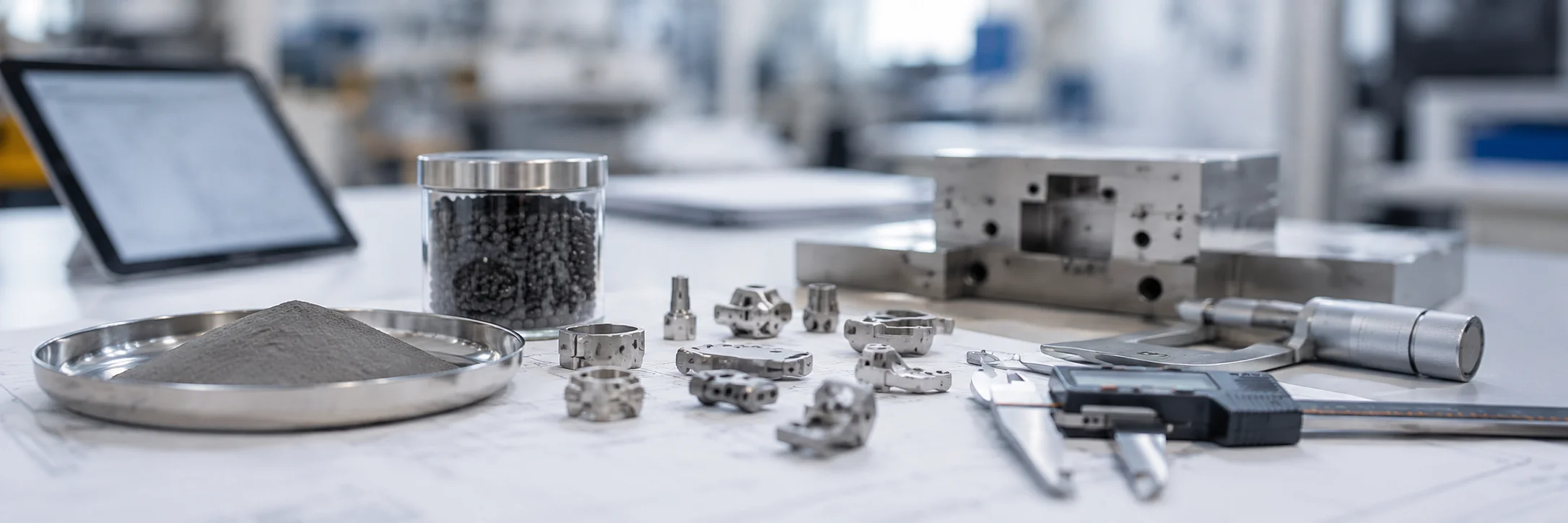
Core conclusion: MIM is not just molding; the final part depends on feedstock, debinding, sintering, tooling compensation, and inspection.
What Is Metal Injection Molding?
Metal injection molding is a metal-forming process that borrows the shaping logic of injection molding but produces a real metal part after debinding and sintering.
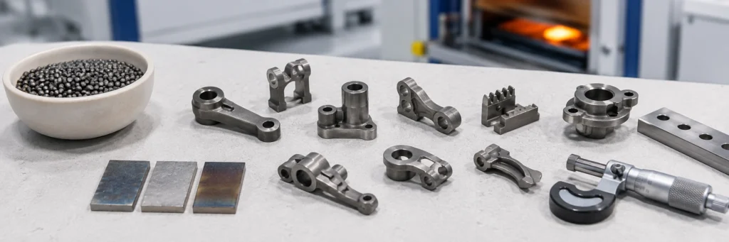
The process starts with very fine metal powder mixed with a binder. This mixture becomes feedstock, which can flow into a mold cavity under injection pressure. After molding, the part is not yet a final metal component. It first moves through the green part, brown part, and sintered metal part sequence before it becomes a finished component after high-temperature densification.
A useful way to understand MIM is this: the mold creates the shape, but sintering creates the final metal structure. This is why MIM is not simply “metal plastic injection molding.” The binder helps the powder flow and hold shape during molding, but the final part depends on debinding, sintering shrinkage, material behavior, dimensional control, and inspection strategy.
A Simple Definition of MIM
Metal injection molding is a process for producing small, complex metal components by molding metal-powder feedstock and then sintering the molded part into a dense metal component. It is most useful when part geometry is too complex for simple powder compaction, too inefficient to machine at volume, or difficult to form as a one-piece metal component by stamping or casting.
Why the “Injection Molding” Name Can Be Misleading
The molding step is similar to plastic injection molding in the sense that feedstock is injected into a mold cavity, but the material system and final part formation are different. In MIM, the molded part is only an intermediate body. It still needs binder removal and sintering before it becomes a functional metal component.
Engineering takeaway: A MIM project should be judged as a complete powder-to-part route, not only as an injection molding operation. The final result is affected by powder size, binder behavior, molded green strength, debinding path, sintering shrinkage, secondary operations, and inspection planning.
How Does the Metal Injection Molding Process Work?
The metal injection molding process is usually explained in linked stages: feedstock, injection molding, green part handling, debinding, sintering, secondary operations, and inspection.
These stages should not be treated as isolated steps. Each stage affects dimensional control, surface condition, strength, cost, and production risk. For a deeper route map, review the MIM process overview.
| MIM Stage | What Happens | Engineering Risk to Review | Why It Matters |
|---|---|---|---|
| Feedstock preparation | Fine metal powder is mixed with a binder system to create moldable feedstock. | Flow stability, binder compatibility, powder loading, and batch consistency. | Feedstock quality affects molding stability, debinding behavior, shrinkage, and final part consistency. |
| Injection molding | Feedstock is injected into a mold cavity to form the green part. | Gate location, filling balance, weld line risk, ejection direction, and green strength. | The molded shape must survive handling and remain suitable for later binder removal and sintering. |
| Green part handling | The molded part is removed and handled before binder removal. | Deformation, cracking, broken thin sections, and handling marks. | Fragile green parts can be damaged before the process reaches the sintering stage. |
| Debinding | Most of the binder is removed by solvent, thermal, catalytic, or combined routes depending on the system. | Incomplete binder removal, internal process risk, distortion, and support method. | Binder removal must be controlled so the part can enter sintering without hidden process risk. |
| Sintering | The brown part is heated so metal particles bond and the component densifies. | Shrinkage variation, distortion, density, support method, and material response. | Sintering determines final metal structure, many final dimensions, and density-related performance. |
| Secondary operations and inspection | Machining, heat treatment, surface finishing, sizing, or inspection may be applied when required. | Critical holes, threads, datum features, cosmetic surfaces, coating requirements, and inspection method. | Some features may still need post-processing or measurement planning even when the part is near-net-shape. |

Core conclusion: Each MIM stage affects final dimensions, density, surface condition, and inspection risk.
Feedstock Preparation
Feedstock is the moldable material used in MIM. It contains metal powder and a binder system. In production, feedstock behavior affects how consistently the material fills the mold cavity, how the molded part holds shape, and how the binder can later be removed. Learn more about MIM feedstock preparation.
Injection Molding and Green Part Formation
During MIM injection molding, feedstock is heated and injected into a mold cavity. The molded part at this stage is called a green part. It has the shape of the component, but it still contains binder and is not yet a final metal part.
Debinding and Brown Part Formation
MIM debinding removes a large portion of the binder from the molded green part. After this stage, the part is commonly called a brown part. Poor binder removal can create process risk that may only become visible later.
Sintering and Shrinkage
During the MIM sintering process, the debound part is heated so metal particles bond together and the part densifies. MIM sintering shrinkage is expected and must be compensated in tooling and process planning.
Secondary Operations
A sintered MIM part may still require sizing, machining, heat treatment, polishing, coating, or other finishing work depending on drawing requirements. This is why MIM should be described as near-net-shape, not automatically zero-machining.
Inspection
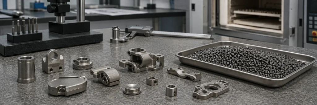
Critical dimensions, datum references, holes, threads, surface condition, and functional features should be inspected according to the part’s application and drawing requirements. Inspection planning should be defined before tooling where possible.
What Types of Parts Are Suitable for MIM?
MIM is usually considered when a metal part combines small size, complex geometry, repeat production demand, and material performance requirements.
The process is especially useful when the component has features that would be expensive to machine one by one or difficult to form with conventional pressed powder metallurgy. For a deeper part-fit discussion, review parts suitable for metal injection molding and the broader metal injection molding applications page.
| Part Condition | MIM Fit | Engineering Reason | What to Check Before Tooling |
|---|---|---|---|
| Small metal part with complex geometry | Strong fit | MIM can form molded features that may reduce machining or assembly. | Feature depth, gate position, parting line, ejection, and sintering support. |
| Thin walls, slots, undercuts, small holes, or fine features | Possible fit | Moldability, tool design, and sintering behavior must be reviewed. | Minimum wall stability, filling path, binder removal path, and distortion tendency. |
| Repeat production with stable demand | Stronger fit | Tooling cost can be distributed across repeated production. | Annual volume, lifetime volume, revision risk, and transfer timing. |
| Simple, flat, or low-complexity geometry | Usually weaker fit | Stamping, PM, CNC, or casting may be more economical. | Whether conventional PM, stamping, or CNC already meets cost and tolerance targets. |
| Very large or heavy part | Usually weak fit | MIM is generally better suited to smaller precision components. | Part mass, maximum envelope, shrinkage control, and furnace support risk. |
| Prototype-only or very low-volume project | Often weak fit | Tooling investment may be difficult to justify. | Whether the prototype is a bridge to production or only a one-time validation part. |

Core conclusion: MIM value increases when small size, complex geometry, repeat production, and material requirements align.
Small and Complex Metal Parts
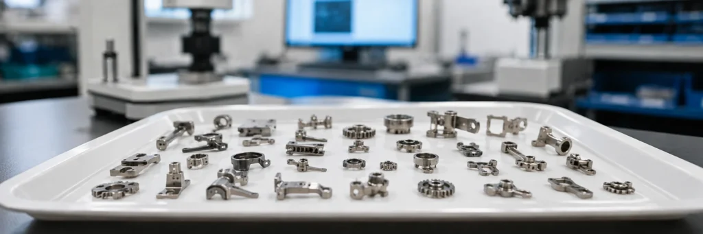
MIM is often reviewed for small components with complex geometry, such as mechanisms, locking parts, connectors, small gears, brackets, precision inserts, hinge components, and structural metal parts used in compact assemblies. The key is not simply that the part is small. The value comes from combining small size with shape complexity, production repeatability, and material requirements.
Thin Walls, Fine Features, and Internal Geometry
MIM can be useful when a part includes thin walls, ribs, grooves, small holes, curved surfaces, or features that would require multiple CNC operations. However, these features still require moldability review for flow, gate position, ejection, green strength, debinding, and sintering support.
High-Volume or Repeat Production Requirements
Tooling is one of the main cost drivers in MIM. For that reason, MIM becomes more attractive when the part has repeat production demand. A single prototype or very low-volume order is usually not the best reason to choose MIM unless the project is preparing for future production.
Parts That Need Material Strength After Sintering
MIM can produce dense metal parts, but final properties depend on the material system, sintering route, density, heat treatment, and part geometry. Each project still requires material and performance review before tooling.
What Parts Are Usually Not a Good Fit for Metal Injection Molding?
A reliable MIM explanation should also explain where MIM is not the right direction. This improves project screening and prevents the process from being treated as a universal replacement for CNC machining, casting, stamping, or powder metallurgy.
Very Large or Heavy Parts
MIM is generally not the first choice for large, heavy components. The process is better suited to small precision parts where molded geometry and sintered metal properties can offset tooling and process complexity.
Simple Parts Better Suited to PM, Stamping, or CNC
If a part has a simple shape that can be produced by conventional PM pressing, stamping, die casting, or basic CNC machining, MIM may not be the most economical route. The correct question is not whether MIM can make the part, but whether MIM improves the project’s total manufacturing logic.
Low-Volume Projects With High Tooling Sensitivity
MIM requires tooling, so low-volume projects should be reviewed through tooling amortization rather than part complexity alone. This does not mean low-volume MIM is impossible, but it does mean the team should confirm whether the project is a one-time prototype, a bridge to production, or a repeat production program before treating MIM as the default route.
Parts Requiring Unverified Materials or Extreme Tolerances
MIM material choice depends on feedstock availability, sintering behavior, and final performance needs. If a project requires an unusual alloy, an unverified material condition, or extremely tight tolerances across many features, the engineering team should review feasibility before tooling.
Cost boundary: For cost-specific decisions, tooling amortization, annual volume, and secondary operations should be reviewed through the metal injection molding cost page rather than forcing this definition article to become a full cost guide.
How Is MIM Different from PM, CNC Machining, Die Casting, and Plastic Injection Molding?
MIM is best understood as one option in a manufacturing process selection decision. It is not automatically better than PM, CNC, die casting, stamping, or plastic injection molding.
| Process | Main Forming Logic | Typical Strength | When to Review MIM Instead |
|---|---|---|---|
| Conventional PM | Powder is compacted in a die, then sintered. | Cost-efficient for many regular shapes and porous parts. | When geometry is too complex for compaction direction limits. |
| CNC machining | Material is removed from bar, plate, casting, or blank. | Flexible for low volume, precision features, and prototypes. | When repeat production machining cost becomes too high for small complex parts. |
| Die casting | Molten metal is injected into a die. | Useful for many castable shapes and larger production programs. | When a small dense precision component needs MIM-suitable material and geometry. |
| Plastic injection molding | Polymer melt is molded and cooled. | Excellent for plastic parts. | MIM uses similar shaping logic but produces a sintered metal component. |
| MIM | Metal-powder feedstock is molded, debound, and sintered. | Useful for small complex dense metal parts. | Best reviewed when geometry, volume, material, and tooling economics align. |
This article only gives a lightweight comparison. For design rules, use the MIM design guide. For general strengths and limitations, use the metal injection molding advantages and limitations page.
Why Does MIM Require Tooling and Engineering Review?
MIM requires engineering review because the final component depends on more than mold shape.
The mold must anticipate sintering shrinkage, the feedstock must flow through the geometry, the green part must survive handling, the binder must be removed without damaging the part, and the sintered component must meet dimensional and functional requirements.

Core conclusion: A part that can be molded still needs engineering review before tooling and quotation.
Tooling Compensation and Sintering Shrinkage
Sintering shrinkage is expected in MIM. The tool cavity is not simply a copy of the final part. It must be designed with shrinkage compensation and process behavior in mind. This is why the supplier needs a real drawing and model before giving a responsible feasibility opinion.
Gate Position, Parting Line, and Molded Feature Review
Gate position, parting line, wall thickness, feature depth, ejection direction, and potential knit lines all affect moldability. If these issues are ignored before tooling, the project may face process risk or expensive tool corrections later.
Inspection Datum and Critical Dimension Review
A drawing may contain many dimensions, but not all dimensions carry the same functional risk. MIM project review should identify critical dimensions, datum references, mating surfaces, holes, threads, and features that may require secondary machining or dedicated inspection and testing.
Why Drawings Matter Before Quotation
A useful MIM quotation usually requires more than a part name. The supplier needs a 2D drawing, 3D model, material target, annual volume, tolerance requirements, surface finish expectations, and application context.
Composite engineering scenario for RFQ review: A small latch or hinge component may look like a strong MIM candidate because it has thin walls, internal features, and multiple machined-looking surfaces. During review, the team still needs to check whether the wall thickness is moldable, whether the gate location can avoid functional surfaces, whether sintering shrinkage can be controlled, whether any hole or thread should remain machined, and whether the expected annual volume can support tooling investment.
| Review Question | Why It Matters Before Tooling | Possible Outcome |
|---|---|---|
| Can the part fill reliably? | Feedstock must flow through thin, deep, or multi-directional features without creating unstable molding risk. | Gate change, wall transition adjustment, or geometry review. |
| Can shrinkage be controlled? | Final dimensions depend on sintering shrinkage, support method, and material response. | Tool compensation review, datum planning, or secondary operation planning. |
| Are all tolerances suitable as-sintered? | Some dimensions may need machining, sizing, or special inspection after sintering. | Separate as-sintered and secondary-machined requirements. |
| Is the annual volume realistic? | Tooling cost must be justified by repeat production or strategic project value. | Proceed to MIM, keep CNC for low volume, or review a staged development plan. |
What Should You Prepare Before Asking a Supplier About MIM?
Before asking a supplier whether MIM is suitable, prepare information that allows engineering review rather than only price guessing.
| RFQ Input | Why It Matters | What the Supplier Checks |
|---|---|---|
| 2D drawing | Shows dimensions, tolerances, materials, notes, and functional requirements. | Critical dimensions, datum strategy, surface finish, and secondary operation needs. |
| 3D model | Helps review geometry, wall thickness, undercuts, and tooling direction. | Moldability, ejection direction, gate location, wall transitions, and support risk. |
| Target material | Determines feedstock availability, sintering behavior, and post-processing route. | Material family, density expectations, heat treatment, corrosion, wear, or magnetic requirements. |
| Annual volume | Helps judge whether tooling investment can be justified. | Tooling amortization, production method comparison, and project timing. |
| Critical dimensions | Identifies features that may need tighter process control or secondary machining. | As-sintered tolerance potential, machining allowance, and inspection method. |
| Surface finish requirement | Influences polishing, blasting, plating, PVD, passivation, or other finishing decisions. | Cosmetic surface control, coating compatibility, and post-processing route. |
| Application or assembly function | Helps identify load, wear, corrosion, magnetic, cosmetic, or regulatory expectations. | Functional risk, mating surfaces, operating environment, and inspection focus. |
| Current manufacturing process | Helps compare whether MIM may reduce machining, assembly, or tolerance stack-up. | Whether MIM should replace, support, or stay behind the current process. |

Core conclusion: Better RFQ information helps the supplier judge whether MIM is technically and commercially suitable.
Drawing and 3D Model
A drawing and 3D model are the starting point for MIM feasibility review. The 3D model helps evaluate geometry, while the drawing shows tolerances, notes, material, surface finish, and inspection requirements.
Material or Performance Requirements
Material selection should not be treated as a simple alloy-name match. The team should confirm whether the target material is available in MIM materials and whether the final part requires corrosion resistance, hardness, strength, magnetic behavior, wear resistance, or surface finishing.
Annual Volume and Project Stage
Annual volume affects whether MIM tooling can be justified. The project stage also matters. A design concept, prototype, pilot batch, and production transfer project should not be quoted in the same way.
Critical Dimensions and Surface Finish Expectations
Critical dimensions and surface finish requirements often decide whether secondary operations are needed. Before quotation, the engineering team should identify which dimensions are functional, which surfaces are cosmetic, and which features can remain as-sintered.
For a more structured checklist, use the MIM RFQ preparation guide before submitting the project.
How This Guide Supports Metal Injection Molding Project Decisions
This guide answers the basic question: what is metal injection molding? After that, the user should move into a more specific decision path.
If You Need Service Capability
Review XTMIM’s metal injection molding services page for production support, capability scope, and supplier-side project review.
If You Need Process Details
Continue to the MIM process overview and individual process pages for feedstock, injection molding, debinding, and sintering.
If You Need Cost or DFM Review
Use the metal injection molding cost page and MIM design guide for more specific project review.
If You Are Ready to Submit a Drawing
Send your 2D drawing, 3D model, material target, annual volume, critical dimensions, and surface expectations through submit drawing for review.
FAQ
Is metal injection molding the same as plastic injection molding?
No. MIM uses an injection molding step, but the material is metal-powder feedstock, not ordinary plastic resin. The molded green part must still go through debinding and sintering before it becomes a final metal component.
Is MIM stronger than powder metallurgy?
Not automatically. MIM often supports higher density and more complex geometry than many conventional pressed-and-sintered PM parts, but final performance depends on material, density, sintering, heat treatment, part geometry, and application requirements.
Why is MIM tooling needed?
MIM uses a mold to form the feedstock into the green part. The tool must account for part geometry, gate position, ejection, shrinkage compensation, and repeat production. This is why MIM normally requires tooling review before quotation.
Can MIM replace CNC machining?
Sometimes, but not always. MIM is worth reviewing when a small complex metal part requires repeat production and CNC machining cost becomes inefficient. CNC may still be better for prototypes, low-volume work, very tight local features, or parts that need machining from solid stock.
What files should I send for a MIM feasibility review?
Send a 2D drawing, 3D model, target material, estimated annual volume, critical dimensions, surface finish requirements, and application context. This information helps the supplier judge whether MIM is technically and commercially suitable.
Technical References
Selected industry references for MIM terminology, process stages, and general process-fit boundaries. These sources do not imply certification, approval, or endorsement of XTMIM.
- MPIF — Metal Injection Molding — Background on molding, binder extraction, and sintering.
- MIMA — Process Overview: MIM — Overview of feedstock, molding, binder removal, and sintering.
- EPMA — Metal Injection Moulding — Background on complex-shaped part fit and process boundaries.
After the basic process background is clear, the next practical step is to check whether a specific drawing, material target, tolerance set, and annual volume make sense for MIM.
Review Whether Your Part Is Suitable for MIM
If your team is reviewing whether a small complex metal part may be suitable for MIM, start with the drawing, 3D model, target material, annual volume, and critical dimensions. XTMIM can review whether the part should move toward metal injection molding, remain with the current process, or require design changes before tooling.