MIM Parts Engineering Guide Quick Answer: What Are MIM Parts? MIM parts are finished metal components produced through metal injection molding. In this route, fine metal powder feedstock is injection molded into a green part, debound, sintered, and inspected into a usable metal component. In practical engineering terms, a MIM part is not a material …
MIM Parts Engineering Guide
Quick Answer: What Are MIM Parts?
MIM parts are finished metal components produced through metal injection molding. In this route, fine metal powder feedstock is injection molded into a green part, debound, sintered, and inspected into a usable metal component.
In practical engineering terms, a MIM part is not a material name, a plastic molded part, or a standard catalog item. It is a metal part whose manufacturability depends on geometry, wall thickness, feedstock availability, shrinkage behavior, tooling compensation, secondary operations, and inspection strategy.
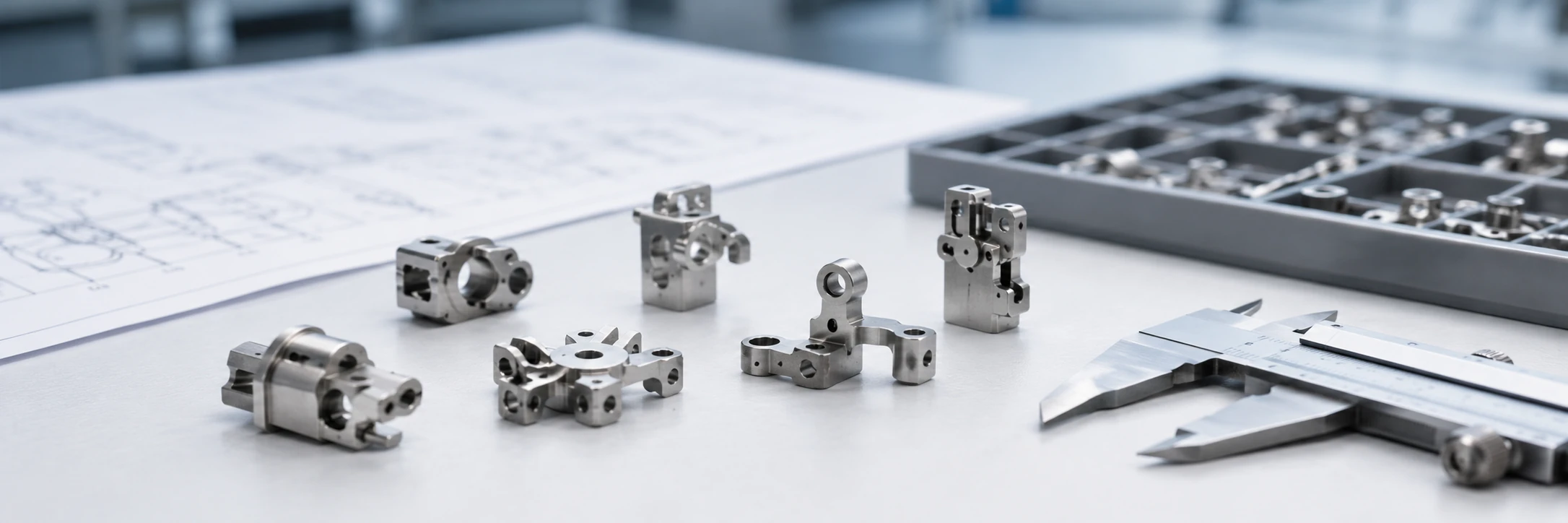
Core conclusion: A MIM part is defined by its manufacturing route and engineering review logic, not only by its final metal appearance.
What Are MIM Parts?
MIM parts are metal components produced through metal injection molding. The process combines powder metallurgy and injection molding principles: fine metal powder is mixed with a binder system into feedstock, molded into a shape, debound, and sintered into a solid metal part.
For engineers and sourcing teams, the important point is this: “MIM part” describes a manufacturing route, not a single material, shape, or product category. Two parts may both be made from stainless steel, but only the one produced through the MIM route should be described as a MIM part.
A practical definition for engineers and sourcing teams
A practical definition is: MIM parts are small to medium-small metal components made from metal powder and binder feedstock through injection molding, debinding, sintering, and final inspection, usually selected when complex geometry, integrated features, material density, and repeatable production are important.
This definition matters because many early RFQ discussions use “MIM parts” too broadly. A part may look small and complex, but it still needs review for wall thickness, flow length, gate position, shrinkage direction, critical dimensions, and whether the expected production volume can justify tooling.
Why “MIM part” describes a manufacturing route, not just a shape
A MIM part is not defined only by its final appearance. It is defined by how the shape is created and how the metal structure is formed after sintering. This affects tolerance planning, surface condition, material selection, cost structure, and inspection.
A common mistake is to look at a compact metal component and assume it is automatically a MIM part. In reality, some small components are better machined, stamped, die-cast, or pressed by conventional powder metallurgy. The MIM route becomes useful when the geometry and production logic fit the process.
| MIM parts are | MIM parts are not |
|---|---|
| Metal components made by metal injection molding | Plastic injection molded parts |
| Produced from metal powder and binder feedstock | A single material grade |
| Shaped by injection molding, then debound and sintered | Standard catalog parts that fit every project |
| Often used for small, complex, high-density metal components | Automatically suitable just because a part is small |
| Reviewed through geometry, tooling, shrinkage, material, and inspection logic | Guaranteed to avoid all secondary operations |
Engineering boundary: Calling a component a MIM part only confirms the intended manufacturing route. It does not automatically confirm that the material is available as feedstock, that all tolerances can be held after sintering, that every feature can be molded directly, or that the project volume can justify tooling.
For a category-level view of actual component families, use the main MIM parts page as the navigation hub. This article focuses on the meaning and engineering logic behind the term.
How Are MIM Parts Made?
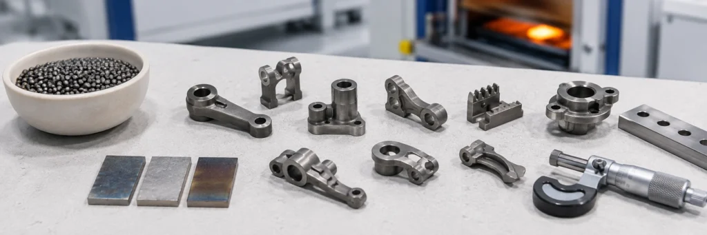
MIM parts are made through a controlled manufacturing route that converts metal powder feedstock into a sintered metal component. The simplified route is feedstock selection, injection molding, green part handling, debinding, sintering, secondary operations where required, and final inspection.
This process path is important because the final part dimensions are not created only by the mold cavity. Shrinkage, tool compensation, sintering support, material behavior, and inspection datum strategy all influence the final result. For a deeper process overview, see the MIM process page.

Core conclusion: The final MIM part depends on molding, debinding, sintering shrinkage, and inspection—not only the mold cavity.
Feedstock and injection molding
The feedstock contains fine metal powder and binder. During injection molding, this feedstock is shaped inside a mold, similar in principle to plastic injection molding but with a metal powder-filled material system. The molded component at this stage is called a green part.
In production, this matters because the green part is not yet a final metal component. It is fragile compared with the final sintered part, and its geometry must survive handling, debinding, and sintering. Thin walls, sharp transitions, unsupported features, and long flow paths may create molding or handling risk.
Debinding, sintering, and shrinkage
After molding, binder must be removed. The part then goes through sintering, where the metal particles bond and the part shrinks toward its final dense form. This shrinkage is a normal part of MIM, but it must be considered during tool design and dimensional planning.
This is one of the main differences between a MIM part and a machined metal part. In machining, material is removed from a solid blank. In MIM, the final shape depends on molding, debinding, sintering shrinkage, and tooling compensation. Readers who need more detail on process-stage terminology can review green, brown, and sintered MIM parts.
Final operations and inspection
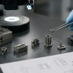
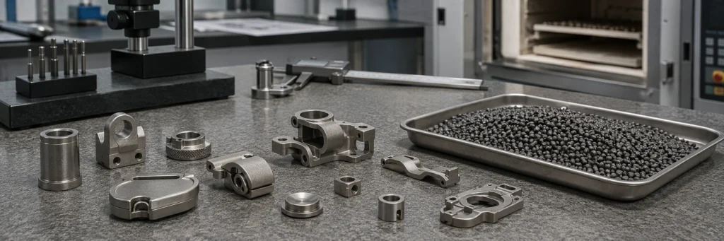
Many MIM parts are near-net-shape components, but that does not mean every feature is finished directly after sintering. Some projects may require sizing, machining, heat treatment, surface finishing, polishing, coating, or inspection of critical features as part of secondary operations.
From a design review perspective, the important question is not only “Can this shape be molded?” The better question is: which surfaces, holes, threads, fits, datum features, and cosmetic areas must meet final requirements after sintering and finishing?
| Process stage | What the part is called | Why engineers should care |
|---|---|---|
| After injection molding | Green part | The shape exists, but the part is fragile and still contains binder. |
| After debinding | Brown part | Binder has been removed, but the part has not yet reached final strength or density. |
| After sintering | Sintered MIM part | The component has shrunk into a dense metal part and must be checked against drawing requirements. |
| After secondary operations | Finished MIM part | Critical features, surfaces, heat treatment, coating, or inspection requirements may be completed here. |
What Makes a Metal Component Suitable as a MIM Part?
A metal component may be suitable for MIM when its geometry, material, size, production volume, and inspection requirements align with the process. MIM is usually considered for parts that are too complex or costly to machine in volume, too three-dimensional for stamping, too small or detailed for die casting, or too complex for conventional powder compaction.
Suitability is not determined by one feature alone. A small part is not automatically a good MIM part, and a complex part is not automatically impossible for other processes. The project should be reviewed as a combination of geometry, function, material, quantity, tolerance, and secondary operations.
| Early fit signal | Why it may support MIM review | What still needs checking |
|---|---|---|
| Small complex metal geometry | May reduce repeated machining or multi-part assembly | Wall thickness, gate location, green strength, sintering support |
| Integrated holes, slots, grooves, or undercuts | May fit injection molding better than pressing or stamping | Tooling release, parting line, core features, inspection access |
| Repeat production demand | Tooling cost can be spread across production volume | Annual volume, design stability, project life, sampling plan |
| Functional material requirement | MIM can support selected engineering alloy routes | Feedstock availability, heat treatment, surface finish, application environment |

Core conclusion: A part may look suitable for MIM, but geometry, wall thickness, shrinkage, tolerance, and volume still need review.
Small size and complex geometry
MIM is often considered when a part is relatively small and has complex geometry such as thin walls, small holes, grooves, undercuts, internal forms, or multiple functional features. These features may be difficult to machine efficiently or may require several operations if made by CNC.
However, “complex” does not always mean “suitable.” A design may still have molding risks, weak green part sections, sintering distortion risk, or inspection challenges. The geometry should be reviewed before tooling instead of judged only by appearance.
Integrated features and reduced assembly
One reason engineers consider MIM is feature integration. A stamped or machined assembly may include several small pieces, welds, pins, or secondary fixtures. In some cases, MIM can convert a multi-piece assembly into one metal component.
This can reduce assembly steps, but it also moves more responsibility into tooling, shrinkage compensation, and inspection. If several functions are integrated into one part, the design team must confirm which features are critical and which can follow normal MIM process capability.
Repeat production after tooling
MIM normally makes more sense when repeat production can justify tooling. For one-off prototypes or very low-volume projects, machining or metal 3D printing may be more practical. For repeat production, MIM can become attractive when the part has complex geometry, stable demand, and enough annual volume to spread tooling cost over many parts.
For a deeper suitability discussion, use the article on what parts are suitable for metal injection molding. This current article only explains the definition and early engineering boundary of MIM parts.
Engineering Decision Module
How to Screen a MIM Part Before Drawing Review
A useful early screening does not ask only whether a component is small or complex. It checks whether the geometry, material, tolerance strategy, annual volume, secondary operations, and inspection plan support the full MIM route from molding through sintering and final acceptance.
The matrix below separates clear MIM fit signals from borderline conditions and strong signals that another manufacturing process may be more practical. It is an early decision tool, not a substitute for project-specific DFM review.
| Decision factor | Usually supports MIM review | Needs engineering review | May favor another process |
|---|---|---|---|
| Geometry | Compact three-dimensional geometry with integrated holes, ribs, grooves, undercuts, or multiple functions | Long thin sections, deep holes, abrupt wall transitions, unsupported features, or difficult ejection | Very simple turned, milled, stamped, extruded, or pressable geometry |
| Part size and section balance | Small to medium-small component with reasonably balanced sections | Local heavy masses, broad flat areas, long spans, or strong thickness variation | Large, heavy, plate-like, or thick-section component with limited geometric value from MIM |
| Production demand | Stable repeat production that can spread tooling cost across the program | Demand is uncertain, design is still changing, or project life is unclear | One-off prototypes or very low-volume production |
| Tolerance strategy | Most features can follow normal MIM capability while a limited number of critical features receive focused control | Several tight dimensions interact across different shrinkage directions or unstable datums | Most surfaces, bores, threads, and fits require precision machining after sintering |
| Material route | Required performance can be met by a practical MIM feedstock, sintering, heat-treatment, and finishing route | Special alloy, density, corrosion, magnetic, hardness, or surface requirements need confirmation | The required alloy or property target is not practical for the available MIM route |
| Feature integration | MIM can combine several functions or replace repeated machining and multi-part assembly | Integrated features increase tooling actions, inspection difficulty, or distortion risk | The part gains little from integration and remains cheaper or simpler in the current process |
| Inspection and acceptance | Critical datums, functional dimensions, surfaces, and test requirements can be defined before tooling | Measurement access, fixture design, cosmetic criteria, or post-processing acceptance remains unclear | The acceptance plan depends on controlling nearly every feature beyond realistic MIM capability |
Failure and selection logic: when an apparent MIM candidate needs to be redirected
| Observed condition | Why it creates risk | Recommended decision |
|---|---|---|
| The part is small but geometrically simple | Small size alone does not create enough tooling or near-net-shape value | Compare CNC, stamping, or conventional PM before selecting MIM |
| The CAD model contains many thin and heavy sections in one component | Different filling, debinding, and sintering behavior may increase cracking, distortion, or dimensional variation | Revise section balance or complete DFM review before quotation finalization |
| Nearly every functional feature needs post-sintering machining | The project may lose the economic and process advantage of near-net-shape production | Separate truly critical features from general features, then compare a hybrid MIM-plus-machining route with CNC |
| The material request is based only on an alloy name used in another process | Feedstock availability, density, heat treatment, corrosion response, and surface condition may differ by route | Confirm the MIM material route and required final properties before tooling |
| Annual volume is unclear and the design is still changing | Tooling investment and shrinkage compensation may be committed before the project is stable | Use prototype or bridge production first, then reassess MIM after the design and demand stabilize |
| The drawing has no defined critical dimensions or inspection datums | Tooling, sampling, secondary operations, and acceptance cannot be planned around real functional priorities | Mark critical features, assembly interfaces, cosmetic zones, and inspection requirements before DFM review |
Decision rule: A strong MIM candidate is not simply a small complex metal part. It is a part whose geometry, material route, production demand, dimensional priorities, post-processing needs, and inspection plan work together as one manufacturable system.
For a deeper suitability assessment, continue to what parts are suitable for metal injection molding. For a drawing-specific manufacturability review, use the DFM for MIM guide before tooling.
MIM Parts vs CNC, PM, Stamped, and Die-Cast Parts
MIM is one metal part manufacturing route, not a universal replacement for every process. CNC machining, powder metallurgy, stamping, die casting, investment casting, and metal 3D printing each have their own process logic. The right choice depends on geometry, volume, material, tolerance, surface requirements, tooling cost, and project stage.
The following comparison is a starting point for engineering discussion, not a final process decision.
| Process route | Usually strong for | Common limitation compared with MIM | Typical review question |
|---|---|---|---|
| MIM | Small, complex, high-density metal parts with integrated features | Requires tooling and shrinkage review | Can the geometry, material, tolerance, and volume justify MIM tooling? |
| CNC machining | Low volume, prototypes, precision local features, solid billet machining | Cost may rise when many small complex features need repeated machining | Which features must remain machined after MIM? |
| Conventional PM | High-volume regular geometry parts suitable for compaction direction | Limited by pressing direction, density distribution, and feature complexity | Is the geometry simple enough for powder compaction? |
| Stamping | Thin sheet metal parts, flat or formed profiles, high-volume sheet components | Less suitable for thick 3D complex features or integrated solid geometry | Is this a sheet metal part or a 3D metal component? |
| Die casting | Larger metal components, castable shapes, higher-volume casting logic | May be less suitable for very small precision features or high-density fine structures | Is the part size, material, and tolerance more aligned with casting? |

Core conclusion: MIM is one metal part manufacturing route, not a universal replacement for every process.
MIM parts vs CNC machined parts
CNC machining removes material from a solid workpiece. It is flexible and useful for prototypes, lower volumes, precision holes, threads, datum surfaces, and features that require tight local control.
MIM forms the part through molding and sintering. In many projects, the best solution may be a MIM near-net-shape part with selected post-sintering machining on critical features.
MIM parts vs PM pressed parts
Conventional powder metallurgy presses powder into a compact, usually along a main pressing direction. It can be cost-effective for high-volume parts with suitable geometry, but it has limitations with side features, undercuts, and deep 3D geometry.
MIM uses injection molding to shape powder-filled feedstock, so it can support more complex three-dimensional geometry when the project also fits tooling and sintering logic.
MIM parts vs stamped or die-cast parts
Stamping is usually strong for sheet metal parts. Die casting is often used for larger cast metal components. MIM is more often considered for compact metal components with small features and three-dimensional geometry.
A common mistake is to compare only part price without comparing design intent. If the current part is a stamped assembly with multiple secondary operations, or a die-cast part that has become too small and feature-dense, MIM may deserve review. The final decision still depends on material, tolerance, size, volume, and tooling feasibility.
Common Types of MIM Parts
MIM parts can appear in many industries, but this article is not intended to be a full MIM parts catalog. The purpose here is to show the kinds of components that often lead engineers to consider the MIM route.
For a complete category-level view, the MIM parts hub should be used as the main navigation page. This article only explains what MIM parts are and why certain part families may trigger an engineering review.
Content boundary: The examples below are intentionally limited. Their purpose is to help readers recognize the kind of part families that may trigger MIM review, while the full category structure remains on the MIM parts hub.
Functional part families
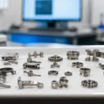
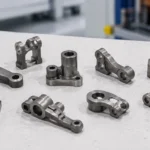
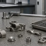
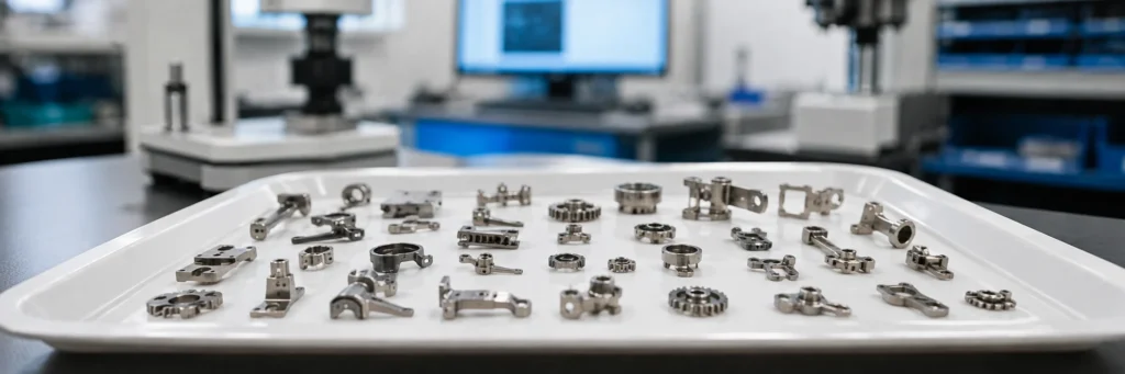
Common functional MIM part families include small gears, micro gears, hinges, brackets, shafts, pins, locking components, connector parts, structural inserts, and small precision mechanisms. These parts often combine compact size with features that would otherwise require multiple machining or assembly steps.
The key point is not the part name. A “gear” or “bracket” is not automatically a MIM part. The geometry, material, tooth form or structural function, tolerance, and production volume must still be reviewed.
Industry-related part examples
MIM parts may be used in consumer electronics, automotive systems, wearable devices, industrial equipment, regulated-device assemblies, locking mechanisms, and small mechanical systems. The specific application matters because each industry may have different expectations for strength, corrosion resistance, wear behavior, surface finish, magnetic behavior, or inspection documentation.
For example, a small consumer electronics component may be reviewed for cosmetic surface and dimensional fit, while an industrial mechanism component may be reviewed for wear, strength, or repeated motion. The same MIM process family may be used, but the engineering review focus is different.
When examples still need drawing review
Examples are useful for understanding process potential, but they should not replace drawing review. A part that looks similar to a successful MIM component may still fail the review if it has unsuitable wall transitions, unrealistic tolerance requirements, unsupported thin sections, difficult inspection datums, or a material requirement that does not match available feedstock.
Before a project is treated as a MIM candidate, the drawing and application requirements should be reviewed together.
Common Misunderstandings About MIM Parts
Because MIM combines injection molding and powder metallurgy concepts, it is often misunderstood by teams who are seeing the process for the first time.
MIM parts are not plastic parts
MIM uses injection molding as a shaping method, but the final part is metal after debinding and sintering. The binder helps the metal powder flow and be molded; it is removed before sintering.
MIM parts are not simply PM parts
MIM and conventional powder metallurgy both use metal powder, but the shaping methods are different. PM commonly uses compaction in a press, while MIM uses injection molding of powder-filled feedstock.
MIM parts still require tooling and shrinkage review
MIM is not a tooling-free process. A mold is required, and the design must account for shrinkage during sintering, tooling compensation, gate position, parting line, ejector strategy, and sintering support.
Not every small metal part is suitable for MIM
A part may be small but still unsuitable for MIM if it has extreme tolerance requirements, very simple geometry, very low annual volume, unsuitable material requirements, or features that require extensive post-sintering machining.
What Should Engineers Check Before Treating a Design as a MIM Part?
Before treating a design as a MIM part, engineers should review the part as a manufacturing system: geometry, material, tolerance, tooling, shrinkage, secondary operations, inspection, and production volume.
The goal is not to force the design into MIM. The goal is to decide whether MIM can produce the required metal component with a practical balance of cost, quality, lead time, and production repeatability.
| Review area | Engineering question | Risk if skipped |
|---|---|---|
| Geometry | Can the part be molded, handled, debound, and sintered without weak sections or distortion? | The part may look possible in CAD but fail during molding or sintering review. |
| Material | Is the requested alloy practical for available MIM feedstock and the required performance? | The quotation may be based on a material direction that cannot be supported reliably. |
| Tolerance | Which dimensions are truly critical after sintering and which features can use normal process capability? | Too many critical dimensions may drive unnecessary machining, inspection cost, or sampling revisions. |
| Secondary operations | Which holes, threads, sealing surfaces, fits, or cosmetic zones may need post-sintering work? | The project may underestimate cost, lead time, or process route complexity. |
| Volume and project stage | Is the design stable enough and the expected production volume high enough to justify tooling? | MIM may be selected too early for an unstable or low-volume project. |
Geometry and wall thickness
Geometry review should check wall thickness, wall transitions, holes, slots, ribs, undercuts, sharp corners, parting line needs, and possible gate locations. Thin sections may create filling or green strength risks. Heavy sections may behave differently during sintering. Features that look simple on a drawing may still need review if they create long flow paths, unsupported green sections, or difficult sintering support.
Material and performance requirements
MIM materials should be reviewed before tooling. MIM can support many engineering alloy directions, but the practical choice depends on feedstock availability, sintering behavior, required properties, corrosion environment, wear conditions, heat treatment needs, magnetic requirements, and surface finishing. A familiar alloy name does not automatically mean the same performance, density, heat treatment route, or surface condition will be achieved through every manufacturing process.
Critical dimensions and inspection datum
Critical dimensions should be separated from general dimensions. MIM can produce repeatable small parts, but not every feature should be treated as equally critical. Datum surfaces, mating features, holes, threads, sliding fits, cosmetic zones, and assembly interfaces should be marked clearly. This helps decide whether a feature should be molded as-sintered, sized, machined, polished, coated, or reviewed through inspection and testing with a dedicated fixture.
Annual volume and tooling logic
Because MIM requires tooling, annual volume matters. The process is usually more practical when the part has repeat demand and the tooling cost can be spread across production. For unstable designs or very low-volume projects, CNC machining, metal 3D printing, or another route may be better during early validation. For stable repeat-production designs, MIM review can focus on tool strategy, sampling risk, and which features must be controlled after sintering.
Composite field scenario for engineering training: A small hinge or locking component may appear suitable for MIM because it has compact geometry, internal forms, and several integrated functions. However, before tooling, the engineering team still needs to review wall thickness, gate position, sintering shrinkage direction, critical dimensions, material availability, surface finish, and inspection datum strategy.
For broader DFM planning, review the MIM design guide before treating a design as a confirmed MIM candidate.
Next Step: Review Your MIM Part Drawing Before Tooling
If you are evaluating whether a metal component can be made as a MIM part, the next step is not only to ask for a price. A useful review should start with the drawing, material requirement, function, tolerance expectations, annual volume, surface finish, and any known assembly or inspection requirements.

Core conclusion: A useful MIM decision starts with drawing review before tooling, not only with a part name or material request.
What to prepare before requesting a review
| Review item | Why it matters |
|---|---|
| 2D drawing and 3D model | Helps review geometry, dimensions, and manufacturability |
| Material requirement | Confirms whether a practical MIM material route exists |
| Critical dimensions | Identifies which features need tighter control |
| Annual volume | Helps judge tooling and production logic |
| Surface finish requirement | Affects secondary operations and cosmetic review |
| Application environment | Helps review wear, corrosion, strength, heat, or magnetic needs |
| Existing process route | Helps compare MIM with CNC, stamping, PM, casting, or other methods |
When XTMIM can give a more useful process opinion
A more useful MIM review becomes possible when the project team can see both the drawing and the application requirement. Without those inputs, the answer may remain too general.
If your part has small size, complex geometry, integrated metal features, and repeat production demand, it may be worth reviewing as a MIM candidate. If the drawing includes tight local dimensions, threads, special surface requirements, or strict material performance requirements, those items should be discussed before tooling rather than after sampling.
If the part looks suitable, the next decision should be based on drawing review, material confirmation, tolerance priorities, and production volume rather than the part name alone.
Review your metal part before MIM tooling
If your component is small, complex, metal, and intended for repeat production, XTMIM can review the drawing before tooling to check geometry, material direction, critical dimensions, secondary operations, and RFQ readiness.
FAQ About MIM Parts
Are MIM parts real metal parts?
Yes. MIM parts are real metal parts after debinding and sintering. The binder is used to help fine metal powder flow during injection molding, but it is removed before the part is sintered into a dense metal component.
Are MIM parts the same as powder metallurgy parts?
Not exactly. MIM and conventional powder metallurgy both use metal powder, but the shaping methods are different. PM usually relies on powder compaction, while MIM uses injection molding of powder-filled feedstock, allowing more complex small three-dimensional geometries.
What types of parts are commonly made by MIM?
Common MIM part families include small gears, hinges, brackets, shafts, pins, locking components, connector parts, high-precision components, and small mechanism parts. However, each part still needs drawing, material, tolerance, and volume review before being treated as a MIM candidate.
Do MIM parts always need secondary machining?
No. Many MIM parts are designed as near-net-shape components, but some features may still need sizing, machining, heat treatment, surface finishing, polishing, coating, or inspection after sintering. Critical holes, threads, datum surfaces, or tight local tolerances should be reviewed before tooling.
What information should I send to check if my part can be made by MIM?
Send the 2D drawing, 3D model if available, target material, annual volume, critical dimensions, surface finish requirement, application environment, and any existing manufacturing route. These details help the engineering team review whether MIM is practical before tooling.
Does a MIM part mean no machining is needed?
No. MIM is often used for near-net-shape metal components, but some projects still need sizing, machining, heat treatment, surface finishing, polishing, coating, or inspection of critical features. The drawing should identify which features must be controlled after sintering.
Technical References
These external references are included to support the general process definition and MIM / conventional powder metallurgy boundary discussed in this article. They do not replace project-specific material, drawing, tolerance, or RFQ review.
- Metal Injection Molding Association — What Is Metal Injection Molding? Industry reference for MIM as a manufacturing route capable of producing complex-shaped metal parts consistently and reliably.
- European Powder Metallurgy Association — Metal Injection Moulding (MIM) Industry reference for understanding MIM as a route for complex-shape parts in higher quantities and for distinguishing it from conventional pressed-and-sintered PM.
Standards and project review note: MIM part feasibility depends on geometry, material, sintering behavior, secondary operations, and inspection requirements. This article provides practical engineering guidance for early process review. Specific material standards, test requirements, or customer drawings should be confirmed during RFQ and technical review.