MIM vs Stamping / Tolerance Stack-Up Review Tolerance Stack-Up in Stamped Assemblies vs One-Piece MIM Components A practical engineering review for stamped assemblies where several formed parts, holes, joints, and fixtures create final assembly variation. Quick answer: Tolerance stack-up in stamped assemblies becomes important when several formed, punched, welded, riveted, or fixture-located parts must work …
MIM vs Stamping / Tolerance Stack-Up Review
Tolerance Stack-Up in Stamped Assemblies vs One-Piece MIM Components
A practical engineering review for stamped assemblies where several formed parts, holes, joints, and fixtures create final assembly variation.
Quick answer: Tolerance stack-up in stamped assemblies becomes important when several formed, punched, welded, riveted, or fixture-located parts must work together as one functional component. Each individual stamped part may pass its own inspection, but the final assembly can still vary because bend angles, hole locations, joining pressure, fixture repeatability, and datum transfer all add variation.
A one-piece MIM component may reduce these assembly-related variables by integrating multiple features into one molded metal part. However, MIM does not automatically guarantee tighter tolerance. It still requires sintering shrinkage compensation, tooling review, datum planning, possible secondary sizing, and final inspection strategy. The practical review question is whether the current variation is caused by too many joined parts and datum transfers, or by a tolerance requirement that would remain difficult in any manufacturing route.
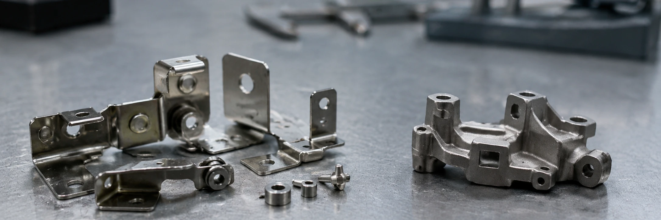
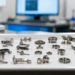
Core conclusion: The visual contrast should show assembly complexity on one side and integrated MIM geometry on the other, without claiming MIM automatically guarantees tighter tolerance.
Why Tolerance Stack-Up Matters in Stamped Assemblies
Tolerance stack-up is an assembly-level problem, not only a part-level problem. In a stamped assembly, the final functional dimension may depend on several separate parts, bends, punched holes, tabs, spacers, rivets, welds, or fixtures. Even when each stamped part stays within its own drawing tolerance, the final assembled position can drift if several tolerances accumulate in the same direction.
This matters because many stamped assemblies are not judged only by the flatness, hole position, or bend angle of each individual part. They are judged by whether the finished assembly locates, rotates, locks, seals, clips, conducts, shields, or supports another component. If the final function depends on the relationship between features across different stamped pieces, the quality risk becomes larger than the tolerance of any single part.
A common mistake is to review only the individual stamped part drawings and ignore the assembled condition. For example, a stamped bracket, a spacer, and a riveted cover may each pass incoming inspection. After riveting, however, the hole-to-surface relationship may shift because the bend angle, rivet compression, fixture location, and part springback all influence the final dimension. In production, this can increase sorting, fixture checking, rework, and assembly-line adjustment.
From an engineering review perspective, the first task is to identify where the tolerance chain closes. If the chain closes inside one stamped part, the issue may be part-level tolerance control. If the chain closes across several stamped parts, fixture locations, and joining operations, the issue is more likely an assembly stack-up problem. That distinction determines whether a one-piece MIM review is worth considering.
| Review Question | Part-Level Tolerance Problem | Assembly-Level Stack-Up Problem | Why It Affects Process Selection |
|---|---|---|---|
| Where is the functional dimension created? | Inside one stamped blank or formed part. | Across two or more joined stamped components. | Assembly-level dimensions may be candidates for part consolidation review. |
| What does inspection measure? | Individual part features only. | Final assembly fit, location, or fixture result. | If the final assembly must be checked repeatedly, the process burden may be hidden in inspection. |
| What creates variation? | Tool wear, material springback, forming variation, or hole position. | Datum transfer, joining force, weld/rivet shift, fixture repeatability, or accumulated part tolerances. | MIM may reduce some assembly variables but still needs its own dimensional review. |
| What should be reviewed first? | Stamped part drawing and forming tolerance. | Assembly drawing, datum scheme, joining method, and final inspection method. | The review should compare finished component control, not only piece-part price. |
Before tooling or process change discussions, the project team should identify which dimensions are truly critical to function. If one functional dimension crosses several stamped components, that area deserves a tolerance stack-up review before deciding whether the existing stamping route should remain unchanged.
Where Variation Accumulates in Multi-Part Stamped Assemblies
Stamped assemblies usually accumulate variation at the points where part geometry, forming, and joining interact. The risk is not simply that stamping is inaccurate. Stamping can be highly repeatable for suitable sheet-metal geometries. The risk appears when several acceptable stamped features must be assembled into one stable 3D relationship.
Bend angles and formed edges
A slight change in bend angle can move a tab, hole, clip surface, or mounting face away from its intended location. If two or more formed parts are joined together, small angular differences can become a larger assembly-level position shift.
Hole-to-hole and tab-to-slot location
Punched holes may be within tolerance relative to the flat blank, but after forming and joining, the effective hole location may depend on bend sequence, fixture setup, and how the mating part is constrained.
Welded, riveted, or mechanically joined interfaces
Joining pressure, heat input, local deformation, part seating, and fixture repeatability may all influence the final geometry. This is especially important when the joined area is close to a critical functional surface.
Fixture location and secondary operations
Trimming, deburring, coining, tapping, machining, grinding, or post-assembly correction may solve one local issue while adding another inspection point or process dependency.
Composite engineering scenario for training: a small stamped assembly uses two formed sheet-metal brackets, a riveted spacer, and a post-assembly locating hole. Each individual stamped part may pass inspection, but the final assembled position varies because bend angle, hole position, rivet compression, and fixture location all affect the same functional dimension. This is the type of assembly where a one-piece MIM review may be useful, provided the geometry, wall thickness, material, shrinkage compensation, and inspection datum strategy are also feasible.

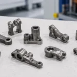
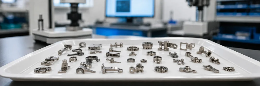
Core conclusion: The image should help readers see that stack-up is created by multiple interacting features, not only by one stamped part tolerance.
| Stack-Up Source | In Stamped Assembly | Why It Matters | MIM Review Angle |
|---|---|---|---|
| Bend angle | Formed features may shift after bending. | Moves tabs, holes, or contact faces. | Can the bend be replaced by molded 3D geometry? |
| Hole position | Holes across separate parts must align. | Drives assembly fit and functional location. | Can key holes or bosses share one molded datum scheme? |
| Weld / rivet / staking | Joining may deform or shift parts. | Adds process-dependent variation. | Can the joint be eliminated by part consolidation? |
| Fixture location | Final assembly depends on fixture repeatability. | Adds inspection and setup burden. | Can final inspection be simplified around one part? |
| Secondary correction | Post-forming correction adds cost and variation. | Increases rework and lead-time risk. | Can near-net MIM reduce repeated correction steps? |
How One-Piece MIM Components Can Reduce Assembly Variation
One-piece MIM does not reduce tolerance stack-up because it is automatically more accurate than stamping. It can reduce stack-up when the main problem is the number of parts and interfaces needed to create the final function. If a stamped assembly uses several pieces to create a 3D shape, a MIM component may combine those features into one molded metal part.
Fewer joined parts means fewer accumulated interfaces. A stamped assembly may depend on part A locating part B, part B being riveted to part C, and part C being checked in a fixture. Each transfer can add uncertainty. A one-piece MIM component can sometimes remove these intermediate steps, allowing critical features to be controlled within one tool and one inspection strategy.
Integrated features can also support a more stable datum plan. Bosses, ribs, lugs, small brackets, hinge forms, locating shoulders, and internal features may be molded into one component instead of being formed, welded, or attached later. When the functional features are controlled from a more consistent datum structure, the final part may be easier to inspect and less dependent on assembly fixtures.
This is especially relevant for small metal components where several thin stamped elements are used to create a compact functional mechanism. If the end user is measuring the final assembly rather than individual stamped blanks, a one-piece MIM review can reveal whether the function can be controlled more directly at the part level.
However, part consolidation must be reviewed carefully. MIM has its own design rules. Wall thickness balance, gate location, debinding path, sintering support, shrinkage direction, feature strength, and inspection access all affect whether the integrated design is practical. A stamped assembly should not be converted to MIM only because it has multiple parts. It should be reviewed because those parts are creating measurable quality, assembly, or inspection burden.
What the MIM review must prove
A one-piece MIM review should prove more than “fewer parts.” It should check whether the integrated geometry can be molded, debound, sintered, supported, inspected, and economically produced. The review should also confirm whether the current assembly variation is actually caused by joined interfaces. This is why the stamped assembly should be reviewed through a MIM design review before tooling, rather than treated as a simple one-to-one process switch. If the main issue is an extremely tight functional tolerance on one surface, MIM may still need secondary sizing, machining, or another control method.

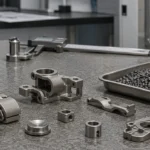
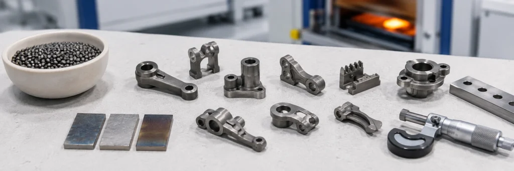
Core conclusion: The image should show structural integration, not imply that MIM automatically guarantees tighter tolerance.
What MIM Still Needs to Control Before It Can Replace a Stamped Assembly
MIM can reduce assembly-related variation, but it introduces process-specific dimensional controls. The project team must review these controls before assuming that a one-piece MIM component will solve the tolerance problem.
Sintering shrinkage and tooling compensation
MIM parts are molded from feedstock and then debound and sintered. During sintering, the part shrinks toward final density. This shrinkage must be considered during tooling and process development. A one-piece MIM part can simplify the assembly chain, but the mold design and sintering behavior must still support the final functional dimensions. For the design-side control topic, review XTMIM’s shrinkage compensation guide rather than treating dimensional control as an automatic outcome.
Datum planning for critical functional surfaces
A stamped assembly may use assembly fixtures as the final reference. A MIM component needs a clear inspection datum strategy. The design team should define which surfaces, holes, bosses, or functional features control the part, and which dimensions are critical to the final system.
Secondary sizing or machining may still be needed
Some MIM components may still need sizing, machining, coining, heat treatment, surface finishing, or other secondary operations depending on tolerance, surface, hardness, or fit requirements. These operations should be reviewed against function, annual volume, inspection plan, and cost target.
Material and geometry suitability
MIM is strongest when the part is small, complex, and suitable for molded metal geometry. Very large sheet-metal panels, simple flat brackets, or low-complexity stamped forms may still remain better stamping candidates.
The key boundary is simple: MIM can reduce some assembly variables, but it does not remove the need for dimensional engineering. If the drawing contains critical datum relationships, tight functional fits, thin sections, unsupported features, or post-sintering flatness requirements, those items should be reviewed before tooling rather than treated as automatic outcomes.

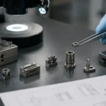
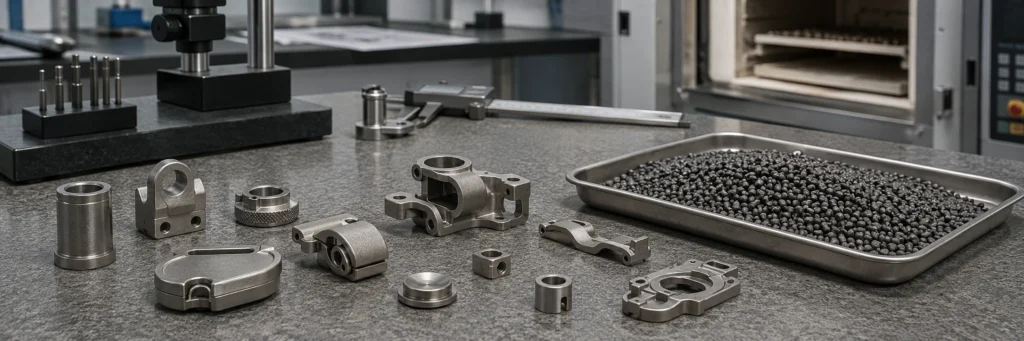
Core conclusion: This image should show that MIM is an engineered process requiring verification, not an automatic tolerance solution.
Stamped Assembly vs One-Piece MIM: Tolerance Risk Comparison
The useful comparison is not “stamping tolerance vs MIM tolerance” in isolation. The useful comparison is where the final functional dimension is controlled. If the functional dimension is controlled across several stamped parts and joining operations, the stamped assembly has more opportunities for accumulated variation. If the functional dimension can be controlled inside one MIM component with a stable datum plan, the MIM route may be worth reviewing.
| Review Item | Stamped Assembly Risk | One-Piece MIM Review Point | Decision Meaning |
|---|---|---|---|
| Number of components | Higher if many pieces define one function. | Lower assembly count, but tooling complexity may rise. | Review MIM if functional dimensions cross several parts. |
| Datum transfer | Multiple datums across parts and fixtures. | More unified datum planning may be possible. | Good candidate if datum chain is hard to inspect. |
| Joining variation | Welds, rivets, staking, or screws can shift features. | Joining may be reduced or removed. | Review if joining drives scrap, rework, or adjustment. |
| Feature-to-feature relationship | Critical features may sit on different stamped pieces. | Integrated features may be controlled in one component. | Stronger MIM case if feature relationships are function-critical. |
| Shrinkage and sintering | Not part of stamping risk. | Must be compensated during MIM tooling and process review. | MIM requires its own dimensional development plan. |
| Inspection burden | Part-level and assembly-level checks may both be needed. | Inspection may shift toward one integrated part. | Review if current inspection is slow, fixture-heavy, or inconsistent. |
| Cost and lead time | Assembly and secondary operations can add hidden cost. | Tooling investment and process development must be justified. | Review annual volume and finished component cost. |
This table should be used as a review guide, not a universal process ranking. A simple stamped part may remain the better solution. A multi-piece stamped assembly with recurring alignment issues may deserve MIM review. For a broader process-selection view, see the XTMIM page on MIM vs stamping process selection.
When a Stamped Assembly Should Be Reviewed for One-Piece MIM
A stamped assembly should be reviewed for one-piece MIM when the assembly process, rather than the individual stamped part, is creating quality risk. The strongest trigger is a functional dimension that depends on multiple stamped pieces.
For example, if a final hole location depends on one bent bracket, one riveted spacer, and one post-assembly fixture, the project team should review whether that relationship can be integrated into one molded part. If the functional surfaces are difficult to inspect after joining, MIM may also be worth reviewing.
Another trigger is increasing inspection burden. If the supplier must inspect each stamped part, then inspect the subassembly, then perform fixture checking or manual adjustment, the finished component cost may be higher than the piece-part stamping price suggests. In that situation, comparing only the unit price of a stamped blank against a MIM part can be misleading.
Secondary correction is also a trigger. If the stamped assembly requires repeated post-forming correction, machining, deburring, grinding, or alignment work, the project may no longer be a simple stamping project. It becomes a finished component control problem. That is where a MIM review can be useful.
A stamped assembly should usually remain stamping when the geometry is mostly flat or lightly formed, the functional dimensions are not sensitive to assembly variation, the part is a large thin panel, the volume or tooling economics do not support MIM, or the material and geometry are not suitable for MIM processing.
Strong review triggers
- One functional dimension is affected by two or more stamped parts.
- The final assembly needs fixture checking, sorting, or manual correction.
- Joining operations shift a hole, face, tab, or locating feature.
- Inspection time is increasing even though individual stamped parts appear acceptable.
- The finished component cost is driven by assembly, rework, and secondary correction rather than the stamped blank itself.
For a related dimensional quality perspective, you can also review how part dimensions affect final MIM part quality. This current article remains focused on assembly-level tolerance stack-up in stamped assemblies.
What to Send for a Tolerance Stack-Up Review
Before asking whether MIM can replace a stamped assembly, the project team should prepare the information that shows where variation actually occurs. A drawing review is more useful when it includes both the individual stamped parts and the final assembly requirements.
The most important file is the assembly drawing. It should show how the stamped parts are joined, which features are functional, and which dimensions control final fit or performance. Individual stamped part drawings are also needed because they show where bend angles, hole locations, tabs, formed edges, and secondary operations may contribute to stack-up.
The datum scheme should be clear. If the current inspection plan uses a fixture, the review should explain how the fixture locates the assembly and which dimensions are checked after joining. If a dimension is critical to function, it should be identified as such rather than hidden inside a general drawing note.
The review should also include the joining method. Riveting, staking, welding, screws, inserts, and press-fit features all influence final assembly behavior. If the current issue involves rework, inspection sorting, inconsistent alignment, field fit, or assembly-line adjustment, that information should be included.
Annual volume and production expectations matter because MIM requires tooling and process development. If the geometry is suitable but the volume is too low, the project may not justify conversion. If the annual volume is stable and the current assembly process is causing recurring variation, MIM may deserve a closer review.
The goal is not to ask for an instant process switch. The goal is to create a review package that allows the engineering team to compare the current finished stamped assembly against a possible integrated MIM component. The review should cover geometry, material, functional dimensions, current inspection burden, secondary operations, expected annual volume, and the reason the current assembly is difficult to control.
| Checklist Item | Why It Matters | What to Highlight |
|---|---|---|
| Final assembly drawing | Shows where tolerance stack-up affects function. | Critical assembly dimensions, mating surfaces, and final fit requirements. |
| Individual stamped part drawings | Identifies which features create variation. | Bends, holes, tabs, formed edges, and secondary operations. |
| Critical-to-function dimensions | Separates important dimensions from general drawing notes. | Dimensions that affect fit, alignment, movement, locking, sealing, or contact. |
| Datum scheme | Helps determine whether inspection can be simplified. | Current inspection datums and how the assembly is located in fixtures. |
| Joining method | Shows whether welds, rivets, staking, or screws are driving variation. | Joining order, joining force, heat input, and location of joined interfaces. |
| Current inspection method | Reveals whether quality control depends on fixture checking or manual adjustment. | Final assembly gauges, fixture checks, sorting steps, and rework points. |
| Current quality issue | Clarifies whether the issue is alignment, rework, fit, scrap, or inspection time. | Which dimension fails, where variation appears, and whether it is batch or fixture dependent. |
| Annual volume | Determines whether MIM tooling review is realistic. | Expected annual demand, project life, and whether assembly labor is recurring. |
| Material and surface requirements | Prevents missing heat treatment, coating, strength, or corrosion requirements. | Material grade, hardness, coating, wear, corrosion, magnetic, or cosmetic requirements. |
| Secondary operation list | Helps compare finished component cost, not only piece-part cost. | Machining, sizing, deburring, tapping, coating, heat treatment, and post-assembly correction. |

Core conclusion: This image should guide users toward submitting the right engineering information instead of asking for a simple process comparison.
FAQ: Tolerance Stack-Up in Stamped Assemblies vs MIM
Can one-piece MIM always reduce tolerance stack-up?
No. One-piece MIM can reduce assembly-related tolerance stack-up when the main variation comes from multiple joined stamped parts, datum transfer, or fixture-dependent alignment. It does not automatically guarantee tighter tolerance. MIM still needs shrinkage compensation, tooling review, datum planning, and inspection strategy.
Why can a stamped assembly vary even when each stamped part is within tolerance?
Each stamped part may pass its own inspection, but the final function may depend on several features across different parts. Bend angles, hole locations, rivets, welds, staking, fixture location, and secondary correction can accumulate variation at the assembly level.
When is stamping still better than MIM?
Stamping may remain better for simple flat parts, lightly formed sheet-metal components, large thin panels, very cost-sensitive simple geometries, or assemblies where the final function is not sensitive to accumulated variation.
What drawings are needed for a MIM review?
A useful review should include the assembly drawing, individual stamped part drawings, datum scheme, critical-to-function dimensions, joining method, current inspection method, current quality issue, material requirement, surface requirement, and expected annual volume.
Does MIM remove the need for inspection?
No. MIM may reduce some assembly-level inspection if several parts are consolidated into one component, but the final MIM part still requires dimensional and functional verification. Critical datums and inspection methods should be defined before tooling.
Should we compare stamping and MIM only by piece-part price?
No. For assemblies with tolerance stack-up problems, the comparison should include finished component cost, inspection effort, joining operations, rework, secondary correction, tooling, process development, and quality risk.
Tolerance Review Boundary Note
Tolerance review should be based on the actual drawing datum scheme, critical-to-function dimensions, assembly method, inspection plan, and production route. This article does not define universal tolerance limits or guaranteed MIM capability. Final tolerance expectations should be confirmed through drawing review, tooling compensation planning, process development, and inspection strategy.
Any stamped-assembly-to-MIM review should compare the finished component, not only the stamped blank or molded part. Assembly labor, fixture checking, joining operations, secondary correction, inspection time, tooling investment, and expected annual volume all affect whether one-piece MIM is technically and commercially reasonable.
Review Whether Your Stamped Assembly Should Become a One-Piece MIM Component
If your stamped assembly is passing part-level inspection but still creating final assembly variation, send the assembly drawing, individual stamped part drawings, critical dimensions, joining method, and current inspection issue for engineering review.