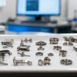
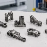
MIM Project Fit Review Metal injection molding is a strong candidate when a small metal component combines complex geometry, repeat production demand, material-performance requirements, and a realistic tolerance strategy. It is not selected only because a part is small, metallic, or costly to machine once. From a design and sourcing review perspective, the practical question …
MIM Project Fit Review
Metal injection molding is a strong candidate when a small metal component combines complex geometry, repeat production demand, material-performance requirements, and a realistic tolerance strategy. It is not selected only because a part is small, metallic, or costly to machine once. From a design and sourcing review perspective, the practical question is whether MIM can reduce repeated machining, assembly, or quality-control complexity without creating new risk in feedstock molding, green part handling, debinding, sintering shrinkage, secondary operations, or inspection.
Quick answer: A metal part may be suitable for MIM when it is small, geometrically complex, needed in repeat production, difficult to machine or assemble economically, compatible with available MIM materials, and able to use a realistic tolerance plan that accounts for sintering shrinkage, secondary operations, and inspection.
Use this page to screen whether a part is worth MIM review before tooling or RFQ.
The decision should combine geometry, volume, material, tolerance, current process cost, and DFM readiness.
A part that is technically moldable may still be commercially unsuitable if volume, tolerance, or process economics do not support MIM.
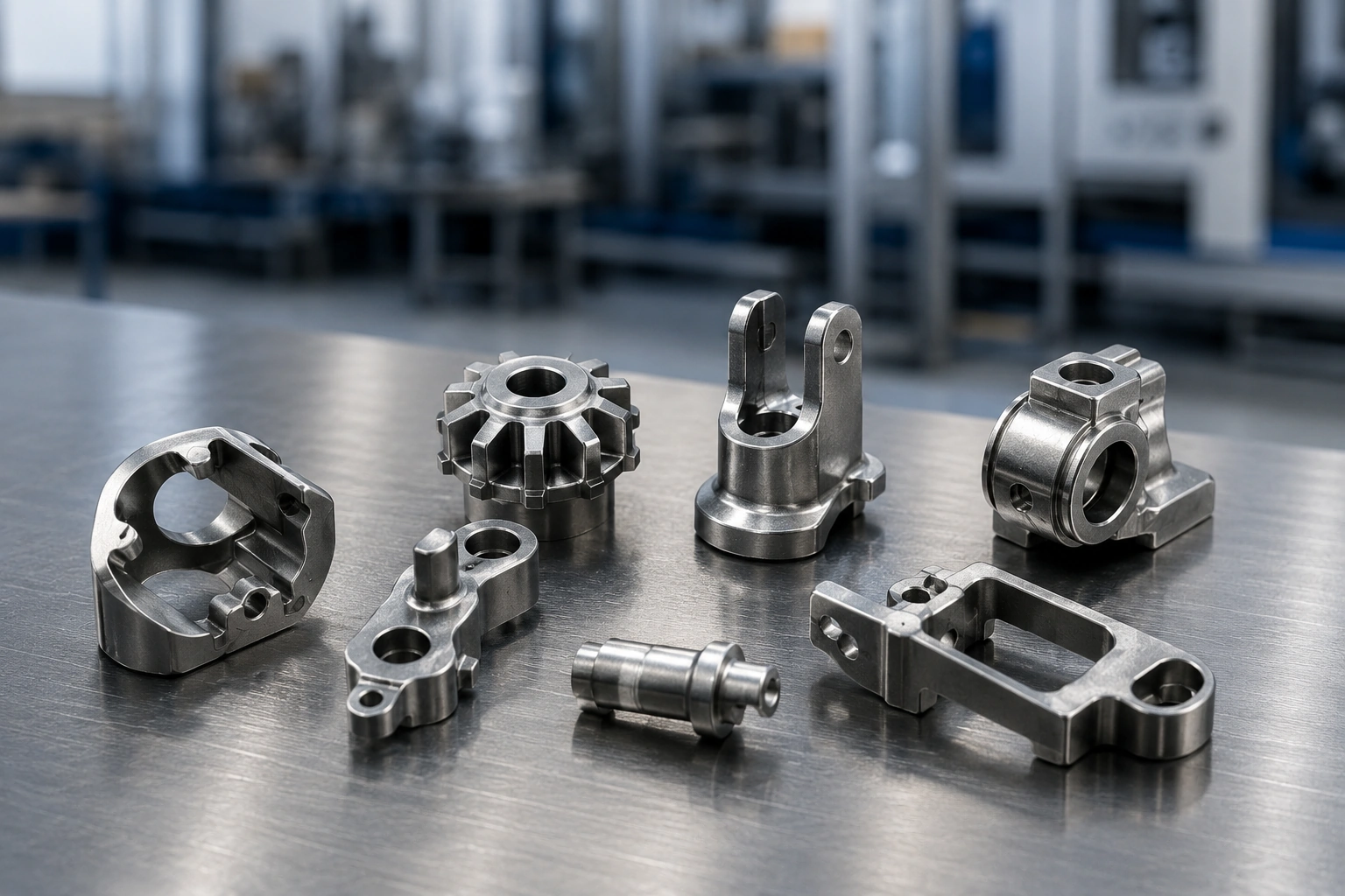
Core conclusion: MIM suitability is an engineering review decision, not a simple “small metal part” judgment.
Quick Fit Check: When a Part Starts to Look Like a MIM Candidate
A MIM candidate usually shows several fit signals at the same time. One positive factor, such as small size, is not enough. The stronger question is whether MIM solves a real manufacturing problem: difficult geometry, repeated machining cost, assembly variation, material performance, tolerance control, or production repeatability.
This page is an early project-screening checklist. For a broader decision covering process selection, when to use MIM, and when another manufacturing route may be better, review the MIM application selection guide.
| Evaluation Factor | Strong MIM Signal | Weak MIM Signal | What to Review Before Tooling |
|---|---|---|---|
| Geometry | Small, complex, multi-feature metal part | Simple flat plate, spacer, or turned part | Can complex features be molded instead of machined? |
| Part Size | Compact precision component with limited mass variation | Large, thick, bulky part | Will shrinkage control and sintering support be practical? |
| Production Volume | Repeat production demand with a stable design | One-off prototype or very low annual demand | Can tooling and development cost be justified over the project life? |
| Material Need | Metal strength, wear resistance, corrosion resistance, magnetic response, or heat resistance matters | Material performance is vague or not critical | Is a suitable MIM material route available for the application? |
| Current Manufacturing Pain | CNC, assembly, casting correction, or yield loss creates recurring cost | Existing process is already simple, stable, and low cost | What problem is MIM expected to solve? |
| Tolerance Strategy | Critical dimensions are identified and realistic | Extreme tolerance is applied across most surfaces | Which features can remain as-sintered, and which may need secondary machining? |
| Review Readiness | 2D drawing, 3D CAD, material, tolerance, and volume are available | Only a photo, sample, or rough concept is available | Can a drawing-based DFM review begin? |
Before choosing MIM, review the full manufacturing route: feedstock preparation, injection molding, green part handling, debinding, sintering shrinkage, dimensional control, secondary operations, and final inspection. The decision should be based on total project feasibility, not only on unit price.
For broader manufacturing context, see metal injection molding. For design-specific checks before tooling, review the MIM design guide.
Signal 1 — The Part Is Small but Geometrically Complex
What this signal means
A strong MIM candidate is often a compact metal component with features that are difficult to machine or assemble repeatedly. Typical examples include thin walls, small holes, ribs, slots, undercuts, micro-features, curved surfaces, gear-like profiles, internal features, side features, and multi-directional geometry.
The important point is not size alone. A small cylindrical spacer may be easier to turn or press by conventional PM. A small component with intersecting features, curved forms, fine details, and multiple functional surfaces may be a better MIM candidate because the geometry can be created by tooling rather than repeated cutting paths.

Core conclusion: Small size is not the same as strong MIM fit. Complex three-dimensional geometry is the stronger signal.
Why it matters for MIM
MIM uses fine metal powder mixed with binder to form feedstock. The feedstock is injection molded into a green part, debound, and then sintered to final density and size. Because the shaping step depends on a mold cavity, MIM can form small three-dimensional features that may require multiple CNC setups, difficult tool access, or separate assembly in other routes.
Complexity still needs review. Thin sections, abrupt thickness transitions, deep blind holes, sharp internal corners, long unsupported features, and poorly placed gates can create filling, ejection, debinding, cracking, or sintering distortion risk. In practice, a CAD model that looks efficient may still need DFM changes before tooling.
What to check before tooling
- Are wall thicknesses reasonably balanced?
- Are there abrupt thick-to-thin transitions that may affect shrinkage?
- Are small holes, slots, ribs, or undercuts realistic for molding and sintering?
- Will undercuts require slides, cores, or design changes?
- Are there unsupported features that may deform during sintering?
- Can gate location and parting line be placed away from critical functional surfaces?
- Which dimensions are critical to assembly, movement, sealing, or inspection?
A complex part is not automatically a good MIM part. It becomes a stronger candidate when the geometry can be molded, debound, sintered, and inspected without excessive secondary correction.
Signal 2 — Multiple Machined or Assembled Features Could Become One Molded Part
What this signal means
MIM often becomes attractive when a design currently requires several small metal pieces, machining operations, joining steps, or alignment processes. If multiple functional features can be integrated into one molded metal component, MIM may reduce part count, assembly labor, positioning variation, and recurring inspection complexity.
This does not mean every assembly should be converted into one MIM part. Consolidation is useful only when the integrated geometry can still be molded, debound, sintered, supported, and inspected reliably.

Core conclusion: MIM fit should be evaluated at the system level: machining, assembly, inspection, alignment, and repeatability all influence whether consolidation makes sense.
Why it matters for project fit
The Metal Injection Molding Association describes MIM design freedom as similar to plastic injection molding while producing a metal component, and it highlights opportunities to combine multiple components and mold functional features from the start. For project fit, this means part consolidation can be valuable when it reduces a real manufacturing or assembly problem rather than only changing the process name.
- too many small parts to assemble;
- alignment variation between components;
- high manual labor content;
- tolerance stack-up across several parts;
- expensive CNC machining of repeated features;
- quality failures caused by joining, press-fit, or handling operations.
What to check before tooling
- whether the integrated shape creates trapped features or difficult ejection;
- whether wall thickness becomes too uneven;
- whether functional datums remain stable after sintering;
- whether bearing, sealing, sliding, or contact surfaces still need machining;
- whether inspection can verify the combined geometry;
- whether tooling complexity offsets the savings from consolidation.
Composite field scenario for engineering training
What problem occurred: A small mechanism was originally made from several machined pieces and a pressed pin. The main issues were assembly variation and rising machining cost.
Why it happened: Each separate part was simple enough to manufacture, but the assembled system created tolerance stack-up. Final function depended on the relationship between several small features after assembly.
What the real system cause was: The cost driver was not only machining time. The larger issue was repeated alignment control across multiple parts.
How it was corrected: The design was reviewed as a possible consolidated MIM component. Several non-critical features were integrated into one molded geometry, while a critical bearing surface remained a secondary-machined datum.
How to prevent recurrence: When reviewing similar projects, compare MIM against the total system: machining, assembly, inspection, alignment, yield loss, and long-term repeatability.
For more geometry-specific guidance, see MIM part design considerations.
Signal 3 — Production Volume Can Justify Tooling and Process Development
What this signal means
MIM is not usually selected for a one-off metal prototype. It requires tooling, feedstock and process validation, shrinkage compensation, trial production, dimensional review, and possible tool correction. These early costs make more sense when the same geometry will be produced repeatedly.
Production volume does not work alone. A high-volume part with simple geometry may still be better suited to PM, stamping, die casting, or automatic turning. A lower-volume part with extremely complex geometry may justify review, but it needs a clear reason beyond “MIM is possible.”
Why volume changes the decision
The practical question is whether MIM improves total project economics over the expected production life. Tooling cost must be weighed against recurring machining cost, assembly cost, scrap risk, secondary operations, inspection workload, and long-term demand stability.
A sourcing manager may ask for unit price first, but a design engineer should first ask whether the part has enough repeat demand and design stability to justify a tooling-based route.
What to send for volume review
- estimated annual volume;
- expected project life;
- first production batch quantity;
- target launch timing;
- current manufacturing process, if any;
- current cost, quality, or assembly pain point, if available;
- whether the part is already released or still under design review.
If the project is still in early development, MIM can still be reviewed, but expectations should be clear. CNC machining or metal 3D printing may be used for early prototype learning, while MIM is evaluated for production feasibility.
For a more complete RFQ input checklist, review the RFQ preparation guide.
Signal 4 — Material Performance Matters More Than Only the Lowest Unit Price
What this signal means
MIM project fit becomes stronger when the part needs both metal performance and complex geometry. Typical drivers may include strength, hardness, wear resistance, corrosion resistance, magnetic response, heat resistance, density, or post-treatment requirements.
A weak fit signal appears when the material requirement is vague. If the part simply needs to be “metal” but has no defined load, environment, wear condition, corrosion exposure, or assembly function, it is difficult to judge whether MIM provides real value.
Why material selection should stay connected to application
Material choice affects feedstock behavior, sintering response, density, strength, heat treatment options, corrosion behavior, hardness, secondary machining, and inspection strategy. It also affects whether a quoted MIM route is realistic for the part geometry and application environment.
This page does not replace a material datasheet or grade comparison. The purpose here is to decide whether material performance is a project-fit signal. Detailed grade selection should be reviewed through the MIM materials section and project-specific drawing review.
What to clarify before material review
- target material grade, if known;
- application environment;
- load, impact, friction, or wear condition;
- corrosion or cleaning exposure;
- magnetic or non-magnetic requirement;
- heat treatment expectation;
- surface finish, coating, or polishing requirement;
- industry or customer specification, if applicable.
A common mistake is to ask whether MIM can make a material before explaining why that material is needed. In production, the better question is: what function must the part survive, and which MIM material route can support that function with acceptable geometry, shrinkage, and inspection risk?
Signal 5 — The Current Process Is Expensive Because of Machining, Assembly, or Yield Loss
What this signal means
MIM may be worth reviewing when the existing process creates recurring manufacturing pain. This often happens when CNC machining needs several setups, small cutters create long cycle time, assembly labor is high, or casting requires heavy post-machining.
The strongest signal is not simply a high current unit price. The strongest signal is a clear cause: geometry, tool access, repeatability, assembly, scrap, or inspection difficulty.
Where MIM may help
| Current Process Problem | Why It Matters | MIM Review Question |
|---|---|---|
| Multiple CNC setups | Increases cost and datum transfer risk | Can near-net molding reduce machining steps? |
| Small holes, slots, or side features | Requires small tools or difficult tool access | Can features be molded with acceptable tooling design? |
| Several parts assembled into one function | Adds labor and tolerance stack-up | Can part consolidation reduce assembly variation? |
| Casting requires heavy machining | Adds correction cost after forming | Can MIM form closer to final shape? |
| PM pressing cannot form side features | Uniaxial compaction limits geometry | Does MIM solve the three-dimensional shape requirement? |
| High reject rate from handling or joining | Quality issue may be system-level | Can a molded metal component reduce process variation? |
What to compare before choosing MIM
- current machining cycle and setup count;
- fixture, cutter access, and tool wear issues;
- assembly labor and alignment risk;
- scrap or rework cause;
- tolerance stack-up across components;
- required secondary operations after MIM;
- inspection method and acceptance criteria;
- expected annual demand and project life.
Composite field scenario for engineering training
What problem occurred: A small metal component was repeatedly machined from bar stock. The part had several side features, a small slot, and a functional contact surface. The CNC cost became difficult to reduce without changing the design.
Why it happened: The geometry required multiple setups and small tools. Even though the part was compact, it was not simple to machine repeatedly.
What the real system cause was: The cost problem came from repeated geometry creation and datum transfer, not from raw material waste alone.
How it was corrected: The part was reviewed for MIM as a near-net-shape candidate. Non-critical features were considered moldable, while the contact surface was kept for secondary finishing.
How to prevent recurrence: When a machined part becomes costly, separate the cost drivers: setup count, tool access, critical surfaces, secondary machining, inspection, and volume. MIM is more likely to help when molded geometry can replace repeated machining work.
Signal 6 — Tolerances Are Realistic for MIM or Can Be Controlled by Secondary Operations
What this signal means
MIM can produce precision metal components, but tolerance strategy must be realistic. A practical drawing usually separates dimensions into three groups:
- dimensions that can remain as-sintered;
- dimensions that require tighter process control;
- critical dimensions that may need secondary machining, sizing, grinding, threading, or inspection focus.
If every dimension is marked as extremely tight, the part may still be possible, but the project may become more expensive, slower to validate, and harder to control in production.

Core conclusion: MIM tolerance strategy should focus on functional dimensions and inspection datums instead of applying extreme tolerance to every feature.
Why tolerance strategy affects project fit
MIM parts go through sintering shrinkage. Shrinkage is planned through tooling compensation, but final dimensional stability still depends on material, feedstock behavior, wall thickness balance, part support, furnace conditions, and geometry symmetry.
Long thin features, uneven wall sections, unsupported arms, and non-uniform mass distribution may increase distortion risk. Critical datum surfaces, mating features, sealing areas, bearing surfaces, or threaded features should be identified early so the supplier can decide whether they can be controlled as-sintered or require secondary operations.
What to check before tooling
| Tolerance Review Item | Why It Matters | Engineering Action |
|---|---|---|
| Critical-to-function dimensions | Not all dimensions need the same control level | Mark CTQ dimensions clearly on the drawing |
| Datum strategy | Inspection depends on stable reference features | Define functional datums early |
| Flatness or straightness | Sintering support and geometry affect distortion | Review support and post-process needs |
| Holes and threads | Small features may need finishing | Decide molded, tapped, reamed, or machined approach |
| Mating surfaces | Assembly risk may drive secondary operations | Confirm contact areas and fit requirements |
| Surface finish | As-sintered surface may not meet all functions | Define finish only where needed |
A practical MIM drawing should tell the supplier which dimensions truly matter. This helps avoid unnecessary cost while protecting the part’s real function. For a deeper tolerance discussion, review the MIM tolerances guide.
Signal 7 — The Design Is Ready for Early DFM Review Before Tooling
What this signal means
A part becomes a stronger MIM candidate when the engineering data is ready for review. A photo, sample, or rough idea may help start a discussion, but it cannot support reliable evaluation of shrinkage, gate location, wall thickness, material route, secondary machining, tolerance strategy, or cost structure.
From a design review perspective, early DFM review is not only a quoting step. It is the point where tooling risk, sintering distortion risk, material fit, tolerance feasibility, inspection method, and production economics are checked before irreversible cost is added.

Core conclusion: Before MIM RFQ, the key issue is not only unit price. The engineering team needs enough project information to evaluate moldability, material route, tolerance risk, and production readiness.
What to send for an initial MIM fit review
| Required Input | Why It Matters |
|---|---|
| 2D drawing with tolerances | Shows critical dimensions, datums, and inspection needs |
| 3D CAD file | Allows geometry, wall thickness, and moldability review |
| Target material or performance requirement | Supports material route and sintering review |
| Estimated annual volume | Helps evaluate tooling economics |
| Surface finish requirement | Clarifies as-sintered vs secondary finish expectations |
| Current manufacturing process | Shows what MIM is expected to improve |
| Application environment | Supports corrosion, wear, heat, or load review |
| Mating parts or assembly requirement | Helps identify functional surfaces and tolerance stack-up |
What an engineering team should review
- geometry suitability;
- wall thickness and thickness transition;
- feedstock and material suitability;
- molding feasibility;
- debinding risk;
- sintering shrinkage and support;
- tolerance strategy;
- secondary machining needs;
- inspection method;
- production volume and RFQ readiness.
To start a drawing-based review, use submit drawings for MIM review.
When These Signals Are Not Enough to Choose MIM
A part can show several positive MIM signals and still fail the final project fit review. “Technically moldable” does not always mean “commercially suitable.” The review must also consider part size, wall balance, tolerance concentration, annual demand, tooling complexity, and whether another process already solves the problem more efficiently.
Parts that may not be good MIM candidates
- the part is large, thick, and simple;
- geometry can be easily produced by CNC turning or milling;
- conventional PM can form the part economically;
- the project is only a one-off prototype;
- annual volume is too low to justify tooling;
- nearly every surface requires tight post-machined tolerance;
- material requirements are unclear;
- the part has severe distortion risk due to long unsupported geometry;
- the customer cannot provide drawings, tolerances, or application conditions.
EPMA describes MIM as a process for complex-shape parts in high quantities and notes that if a shape can be produced by conventional pressing and sintering, MIM may often be too expensive. That boundary is important: MIM should be selected for the right combination of geometry, material, volume, and production value, not simply because the part is metal.
Composite field scenario for engineering training
What problem occurred: A team wanted to convert a simple round metal spacer to MIM because the annual quantity was increasing.
Why it happened: The part was small and metal, so it was assumed to be a natural MIM candidate.
What the real system cause was: The geometry was too simple. The existing process had no major machining complexity, assembly problem, or material-performance constraint that MIM would solve.
How it was corrected: The part was reviewed against CNC turning and PM alternatives. MIM was not selected because tooling and process development did not create enough value.
How to prevent recurrence: Do not judge MIM suitability by size alone. Ask what MIM is solving: complex geometry, part consolidation, recurring machining cost, material-performance need, tolerance strategy, or quality variation.
How XTMIM Reviews a Part for MIM Project Fit
A practical MIM project review should not start with price alone. It should first identify whether the part has a realistic manufacturing path from geometry review to tooling, sintering, secondary operations, and inspection.
Geometry and DFM
XTMIM reviews whether the part geometry supports feedstock injection molding, green part handling, debinding, sintering support, and final inspection. Thin walls, holes, slots, ribs, undercuts, and thickness transitions are checked before tooling.
Material Suitability
The review checks whether the target material or performance requirement matches available MIM material routes. If the material is not fixed, the review focuses on function: strength, wear, corrosion, magnetic response, heat exposure, surface requirement, and post-treatment expectations.
Tooling and Shrinkage Risk
MIM tooling must account for shrinkage and part support. Gate position, parting line, ejection, core features, wall balance, and sintering orientation can affect final quality.
Tolerance and Secondary Operations
The review separates as-sintered dimensions from critical features that may need machining, sizing, threading, grinding, polishing, or tighter inspection.
Production volume and RFQ readiness
The review checks whether production volume, project timing, drawing readiness, and technical requirements are sufficient for meaningful RFQ discussion.
A useful project fit review may confirm MIM suitability, recommend design changes, identify missing information, or suggest another process. That is still a useful result if it prevents tooling risk before cost is committed.
Request a MIM Project Fit Review
If your part is small, complex, difficult to machine repeatedly, or affected by assembly cost, tolerance stack-up, or material-performance requirements, XTMIM can review whether MIM is a realistic production route.
For a useful review, send 2D drawings with tolerances, 3D CAD files, target material or application requirements, critical dimensions, estimated annual volume, surface finish expectations, current manufacturing process, application background, and mating part information.
XTMIM’s engineering team will review geometry, material suitability, wall thickness, tooling risk, sintering shrinkage, tolerance strategy, secondary operation needs, inspection approach, and RFQ readiness before tooling or production planning begins.
FAQ About Metal Injection Molding Project Fit
What types of parts are usually suitable for metal injection molding?
Parts that are small, complex, metallic, and intended for repeat production are usually stronger MIM candidates. Good examples often include parts with thin walls, holes, slots, ribs, undercuts, curved surfaces, or multiple functional features that would be expensive to machine or assemble repeatedly.
Is MIM suitable for low-volume prototypes?
MIM is usually not the first choice for one-off prototypes because it requires tooling and process development. CNC machining or metal 3D printing may be more practical for early prototypes. However, if the part is moving toward production, an early MIM feasibility review can help identify design changes before tooling.
Can MIM replace CNC machining?
MIM can replace some CNC machining when complex geometry can be molded near net shape. It does not always eliminate machining. Critical holes, sealing faces, threads, bearing surfaces, or tight datum features may still require secondary operations.
Is MIM cheaper than CNC machining?
MIM may reduce recurring cost when a part has complex geometry, repeat production volume, and high machining or assembly cost. It is not automatically cheaper for prototypes, simple parts, or low-volume projects because tooling, validation, and possible secondary operations must be considered.
What part size is best for MIM?
MIM is generally reviewed for compact precision metal parts rather than large, bulky components. There is no universal size rule because mass distribution, wall thickness, feature complexity, material, shrinkage behavior, and tolerance requirements all affect project fit.
Is MIM better than PM?
MIM is not simply better than PM. PM is often more cost-effective for relatively simple, press-direction-friendly parts such as bushings, gears, and structural components. MIM is usually considered when the part requires more complex three-dimensional geometry, higher feature integration, or design freedom that conventional powder compaction cannot easily provide.
What information is needed for a MIM project fit review?
A useful review usually needs a 2D drawing, 3D CAD file, material or performance requirement, critical tolerances, estimated annual volume, surface finish requirement, application environment, and any current manufacturing pain points such as machining cost, assembly variation, or quality issues.
What is the biggest mistake when judging MIM suitability?
The biggest mistake is judging by part size alone. A small metal part is not automatically a good MIM candidate. Geometry, volume, material performance, tolerance strategy, tooling economics, secondary operations, and inspection requirements must be reviewed together.
When should a part not be made by MIM?
A part may not be suitable for MIM if it is large and simple, only needed in very low quantity, easy to machine or press by PM, unclear in material requirements, or requires extreme tolerances on nearly every surface. In those cases, another process may be more practical.
Standards and Technical References Note
MIM project fit should be reviewed using both project-specific engineering data and relevant industry references. MIMA’s design information is useful for understanding why MIM can support part consolidation and molded functional features, but it does not replace supplier-specific DFM review.
EPMA’s MIM overview is relevant because it frames MIM as a technology for complex-shape parts in high quantities and explains the economic boundary between MIM and conventional pressing and sintering when the geometry allows a simpler PM route.
MPIF Standard 35-MIM is relevant for material specification because MPIF describes its standards resources as covering MIM materials with explanatory notes and definitions. ASTM B883 may also be relevant when reviewing ferrous MIM material specifications, but it should not be treated as a universal standard for every MIM alloy family or every project requirement.
Final material and process selection should still depend on part geometry, application environment, drawing requirements, feedstock route, secondary operation needs, inspection plan, and supplier capability.