Metal Injection Molding for Small Complex Parts: Size, Volume, Tolerance and CostMetal Injection Molding for Small Complex Parts: Size, Volume, Tolerance and Cost Engineering decision guide • Small complex metal parts Metal injection molding for small complex parts is worth considering when feature-dense geometry makes the existing manufacturing route costly, most of that geometry can …
Engineering decision guide • Small complex metal parts
Metal injection molding for small complex parts is worth considering when feature-dense geometry makes the existing manufacturing route costly, most of that geometry can be molded and sintered reliably, critical functions can be verified, and repeat demand can justify tooling. Small size alone is not a reason to choose MIM. The real question is whether a near-net-shape MIM body, with selective finishing where required, offers a better way to deliver the accepted part.
For a small metal part with side features, steps and precision interfaces, the decision starts with four questions: which recurring operations could disappear, whether the geometry can be molded and sintered, which finished features need separate control, and whether the investment works over the expected production life. The 17-4 PH component discussed later puts those trade-offs into one drawing. For less feature-dense designs, the broader MIM part suitability guide provides a starting point.
01 / GEOMETRYDoes complexity remove real manufacturing work?
02 / PROCESSCan the shape be molded and sintered?
03 / FUNCTIONCan material and CTQ features meet the drawing?
04 / ECONOMICSWill repeat production justify tooling?
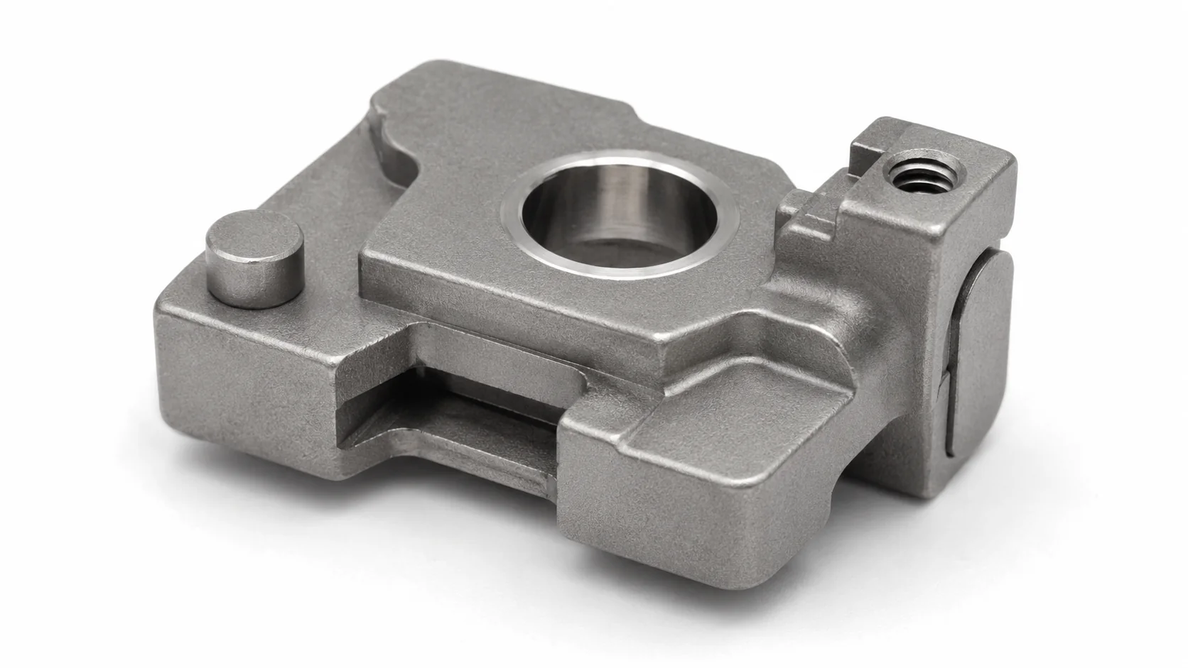
Which Small, Complex Part Features Create a Real MIM Advantage?
Geometry has value for MIM only when it removes significant work from the existing manufacturing route. A compact shape that is already inexpensive to machine may offer little return on a dedicated mold.
Metal injection molding (MIM) injects a metal-powder and binder feedstock into a shaped tool, then removes binder and sinters the compact toward its final dimensions. The commercial advantage comes from reproducing complex geometry with fewer recurring operations, not from making a part smaller. The Metal Injection Molding Association's design guidance explicitly considers shape complexity, material performance, production quantity and component cost together. A promising drawing therefore needs both a geometric reason to mold and a defensible route to acceptable finished parts.
Why Part Size and Weight Alone Do Not Determine MIM Suitability
Imagine two parts with similar envelope dimensions. A plain turned pin may need one bar-feeding and turning setup; replacing that efficient route with injection tooling would add capital and validation without removing much work. A compact locking bracket with offset bosses, a cross-slot and a locating face might require several tool approaches, fixtures and deburring checks. The second part presents a more meaningful potential MIM opportunity because its functional geometry is the source of recurring process complexity. Size and mass still matter for cavity layout, feedstock consumption, handling and furnace loading, but neither establishes a universal pass/fail threshold.
Very small openings, long thin walls, large differences in local mass or fragile projections can also make a physically small part more difficult to fill, eject, debind or sinter. This is why the drawing should be evaluated by feature, function and manufacturability, rather than by dimensions alone.
Practical drawing review: For each feature, record its current operation, setup or handling requirement, its tolerance, and whether it can be molded without an impractical tool action. A small feature that is easy to mill in a single accessible setup may contribute little value. A thin projection that looks moldable in CAD may instead introduce fill, ejection or sintering risk. This feature-by-feature comparison is more informative than a generic size range.
Which Geometric Features Create Repeated Manufacturing Work?
Start with the actual operation sheet, not a count of CAD features. A multi-axis CNC machine may reach a cross-hole and side slot in one setup, while a three-axis route may require repeated repositioning; the machining penalty is different in each case. Likewise, a molded side feature is not a free operation if it needs a moving side core, shut-off maintenance or substantial flash removal. Compare machine minutes, setup and handling, scrap exposure, finishing and inspection rather than assuming one molded feature replaces one complete CNC operation.
| Small-part feature | Potential burden in the existing route | Possible MIM value | What must be checked |
|---|---|---|---|
| Stepped outer profile and bosses | Multiple cutter paths or setups | Form several levels in one molded body | Fill balance, draft, ejection and shrinkage |
| Side slot or cross-hole | Side-access machining, fixture changes, burr removal | Reduce repeated feature machining | Tool pull direction, slides or shut-offs, flash and access |
| Integrated mounts or joining details | Separate parts, fastening and assembly checks | Reduce part count and assembly operations | Tool complexity, tolerances and service loads |
| Precision bearing or locating bore | Finish boring, reaming and measurement | Form the surrounding complex body | Whether post-sinter machining must remain |
| Simple axisymmetric surface | Often efficient turning | May provide little MIM benefit | Actual cycle cost before selecting tooling |
| Cross-hole requiring a side action | Dedicated drilling or multi-axis access, plus exit-burr control | Possibly form the hole in the molding step | Core pin support, deflection, parting-line flash and whether a machined hole is simpler |
A side feature that needs an expensive slide, a difficult shut-off or extensive flash removal can cost as much as the machining it replaces. The benefit must be judged against the complete proposed MIM route—including mold complexity, secondary finishing and inspection—before the part proceeds to detailed DFM.
Example: a cross-slot on a compact bracket. A slot perpendicular to the preferred mold-opening direction can prevent straight-pull release. That is a release-direction conflict, not a problem caused simply by the slot being small. Compare a side-action mold with a different part orientation or post-sinter slot machining; then confirm achievable slot width, flash control and tool maintenance. If the side-action cost outweighs the machining it removes, the slot does not strengthen the case for MIM.
Geometry screening outcome: A part with repeated setups, difficult tool access or avoidable assembly work merits a detailed MIM DFM review. If the geometry is already inexpensive to turn or mill, the tool investment needs a different justification. For the manufacturing implications of densely featured parts, see complex-geometry metal parts.
Can the Part Be Molded, Debound, and Sintered Reliably?
A feature can create cost value and still be unsuitable for a particular mold or sintering setup. The engineering task is to determine which details can be retained, which need redesign and which should be finished later.
Can the Complex Features Be Molded and Released?
Tooling feasibility begins by choosing a plausible parting direction and identifying every feature that would lock the green part into the mold. A through-hole aligned with a supported core may be straightforward, while an internal undercut can require a collapsing core or redesign that is difficult to package in a compact tool. The EPMA MIM design overview notes that internal undercuts are particularly problematic on small MIM parts; external undercuts can also require split cavities and leave witness lines. A feasible CAD solid is therefore not proof of a practical mold. Compare core stiffness, tool opening sequence, ejection forces, flash location and maintenance before classifying a feature as near-net-shape.
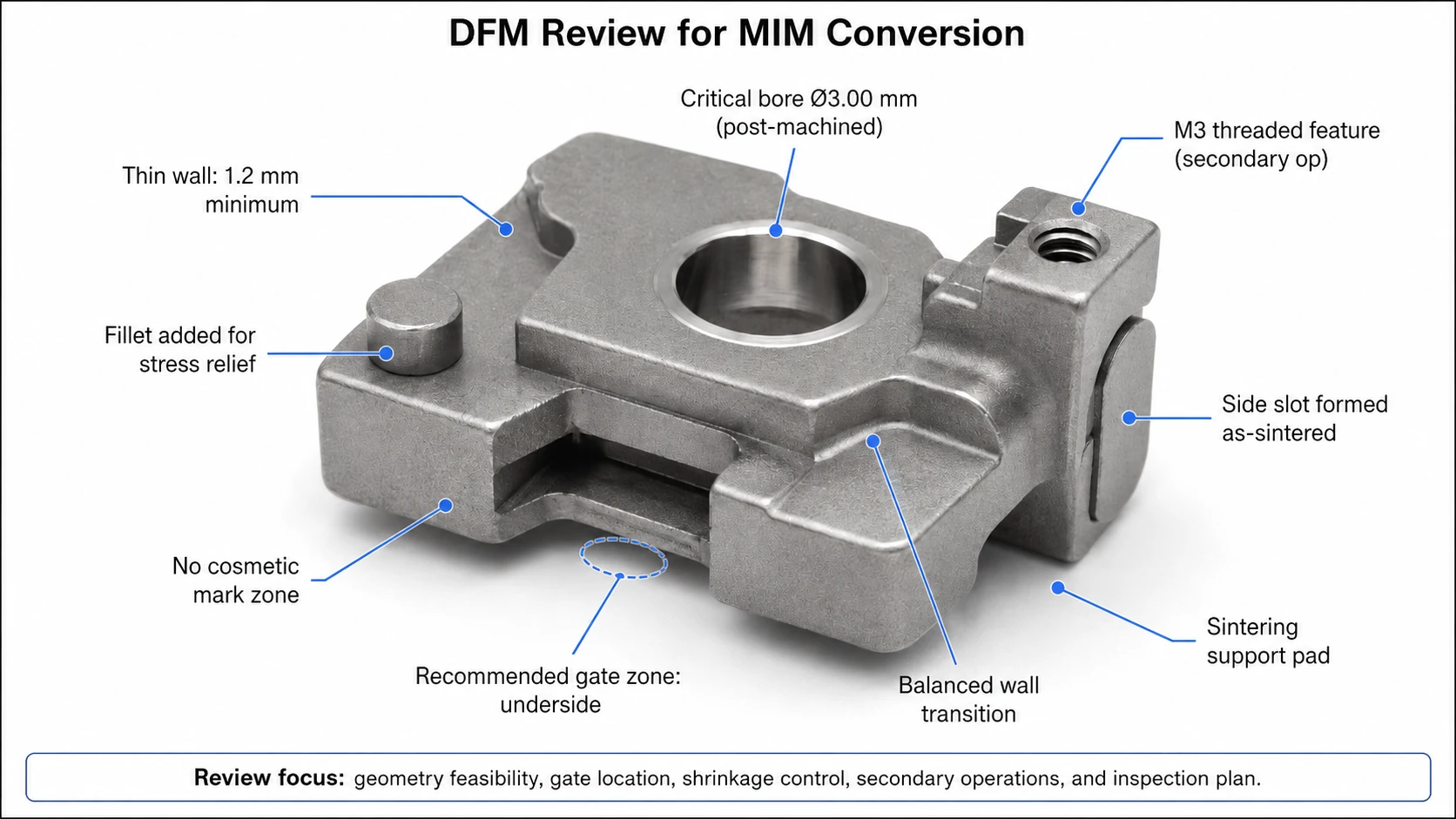
Gate and ejector locations must be chosen against the part's functional surfaces and its expected fill path. Relocating a gate from a visible locating face to an underside zone may avoid a witness mark, but it may also lengthen flow into a thin rib or alter how the feedstock fills a distant boss. Possible consequences include an incompletely filled detail, a visible weld line, local powder-binder segregation or variable green-part packing; the actual cause needs molding trials or process evidence. Mark cosmetic and datum no-contact zones on the drawing, then review filling, release and surface acceptance as one decision. The holes, slots and undercuts guide covers tool-direction details beyond this feasibility assessment.
What to verify before tooling release: the proposed tool opening sequence, minimum core support, location of parting-line witness marks, a feasible ejection path, and whether any machined feature must be left as a pilot or with extra stock. For a transverse hole that locates a mating shaft, also verify that the chosen molded core can keep the hole axis within a realistic position allowance after sintering; nominal hole diameter alone is not enough.
How Do Wall Thickness, Shrinkage, and Sintering Support Affect Stability?
After molding, binder removal has to proceed without damaging a compact whose strength changes as the binder leaves. The EPMA process description notes the fragile condition of the debound compact and the substantial shrinkage associated with sintering. Thick local masses, blind recesses and narrow transitions may lengthen binder-removal paths or create fragile connections between regions. During sintering, differences in green density, gravity and setter contact can change the relative positions of a hole, boss or locating face. A thick boss does not necessarily cause distortion: the stage at which movement first appears must be established from measurements before selecting a corrective action.
Design example: a heavy boss beside a thin web. Consider a locating bore inside a relatively heavy boss connected to an unsupported arm by a thin web. The concern is possible bore-location drift or bowing after sintering. Green-density variation, geometry-dependent densification, gravity and support conditions are different potential causes. Measure the molded geometry and compare it with the same features after debinding and sintering. Movement already present in the green part points toward tooling or molding; movement developing during firing requires attention to sintering conditions and support. Possible changes include reducing local mass, improving section transitions, reorienting the part or introducing controlled support contact. Trials determine which change actually works.
A sintering support is not a universal cure. Contact can reduce unsupported sag but also restrict free shrinkage or leave a surface mark, depending on the material, setter and thermal cycle. Choose support contact surfaces that will not compromise mating geometry, record the orientation and setter material, and compare post-sinter flatness and feature position from controlled trial lots. This is why support planning belongs in drawing-based DFM, with detailed treatment in the sintering support guidance and shrinkage compensation.
| Potential issue | Engineering mechanism | Possible design or process response | Required verification |
|---|---|---|---|
| Side undercut or enclosed slot | Conflicts with a straight tool pull | Assess side action, shut-off, reorientation or later machining | Tool concept, release and flash review |
| Thick boss next to thin section | Uneven local mass and sintering response | Review transitions, radii or local weight reduction | Trial distortion and crack inspection |
| Long unsupported span | Gravity and support-dependent movement during sintering | Orient differently or incorporate a support contact | Flatness and positional checks after sintering |
| Gate or ejector in a functional zone | Witness mark, local geometry or surface interference | Move contact to an acceptable region subject to filling analysis | Visual and function-based acceptance |
| Deep blind recess or trapped internal pocket | Long binder-removal path, cleaning access and weak core support | Review depth, open the feature, add access or machine after sintering | Debinding plan, section inspection and practical cleaning/inspection access |
| Sintering-support contact near a locating face | Contact friction or witness mark may interfere with shrinkage or flatness | Relocate support to a non-CTQ region; compare orientations | Datum flatness, contact marks and position after firing |
DFM outcome: Each important feature should have a defined route: mold as designed, revise and validate, or retain post-sinter machining. If an essential feature requires an impractical tool or cannot survive debinding and sintering, favorable CNC cost alone will not make MIM viable.
Can the Finished Part Meet Material and Critical-Tolerance Requirements?
Successful molding is not the same as an accepted functional component. The relevant question is whether the finished MIM and finishing route can meet the material specification, assembly datums and critical-to-quality (CTQ) dimensions.
Is a Suitable MIM Material and Production Route Available?
Material selection begins with service loads, wear, corrosion and the required final condition rather than the nominal alloy name alone. For a 17-4 PH component, specify the required heat-treatment condition and confirm that the supplier has an established powder/feedstock, debinding and sintering route. Density, composition, strength, hardness and corrosion resistance must be linked to agreed acceptance criteria. The MPIF notice for Standard 35-MIM (2025) identifies updated corrosion-resistance coverage for MIM 17-4 PH. Conformance of a particular lot still depends on the specified condition, applicable test methods and actual material results. Grade-specific selection considerations are covered in the 17-4 PH stainless steel MIM guide.
The material review should record the required final condition, whether heat treatment or passivation follows sintering, what surface or corrosion standard applies, and at which stage the dimensions are accepted. If a required state or inspection method has not been agreed, the material decision remains open even when the geometry looks suitable. Industry material standards support specification writing but cannot replace supplier qualification or part-specific tests.
Which Features Can Remain As-Sintered and Which Require Machining?
The most practical small complex MIM part is not always the one with no machining. A near-net-shape body can preserve multi-level geometry and integrated bosses while precision is applied only where assembly actually needs it. The decision must be made feature by feature. Reaming can improve the size and finish of a bore, and tapping can form a reliable internal thread after sintering, but both require a suitable stock allowance, consistent fixturing and a controlled reference system. Saving a machining operation is not beneficial if the remaining interface fails assembly.
Example: a 3.00 mm locating bore. Consider a finished bore specified as 3.00 to 3.02 mm (Ø3.00 +0.02/0.00 mm). A molded pilot with machining allowance can be reamed after sintering to control diameter and improve finish, but a reamer generally follows the existing pilot axis. Reaming alone cannot be relied on to correct a bore that has shifted out of position. If hole location is critical to assembly, define its relationship to the datums and evaluate locating fixtures, pilot preparation or boring capable of establishing the required axis. Inspect bore size and position separately. A nearby M3 thread can also be evaluated for post-sinter tapping without assuming that molded threads are impossible.
For an as-sintered dimension, the EPMA guidance uses ±0.3% as a general dimensional reference and discusses tighter control on selected, fine-tuned dimensions. That value should be interpreted as a context-dependent screening reference, not a guarantee. For example, 0.3% of a 28.4 mm nominal length is about 0.085 mm, but this arithmetic does not validate the part's actual length, its datum scheme, or a unilateral bore requirement. A drawing and process-capability review are still necessary.
How Should Critical Features Be Verified?
Each critical-to-quality (CTQ) characteristic needs four linked definitions: functional requirement, datum reference, manufacturing stage and acceptance method. A slot that guides a mating tongue may need a width and straightness check after sintering; a reamed bore needs size, axis location and surface verification after the final operation. Flatness must be tied to the intended locating or seating function. For material properties, identify the material condition and applicable test method, not just a target number. Where process capability is required, first confirm a stable process and a suitable measurement system; a Cpk number quoted without drawing revision, sampling plan and measurement study is not enough for production approval.
To diagnose an out-of-position bore: measure the pilot position relative to the agreed datums after sintering, then measure the finished bore after machining. If the pilot has already shifted, investigate tooling location, green-part distortion, sintering support and shrinkage orientation. If the pilot is acceptable but the finished axis moves, inspect machining fixturing, datum transfer and tool path. This separates a MIM process problem from a secondary-operation problem instead of treating every rejected bore as a sintering defect.
| Feature | Potential route | Main functional risk | Evidence required |
|---|---|---|---|
| Outer contour, bosses, steps | Prefer as-sintered where capable | Dimensional drift and local distortion | Defined datums and trial dimensions |
| Side slot | Consider molded feature | Flash, width and wall stability | Feature measurements or go/no-go gauge |
| Precision Ø3.00 mm bore (illustrative) | Mold with allowance; ream after sintering | Assembly fit and bore position | Bore size, position and measurement record |
| M3 thread (illustrative) | Mold pilot; tap after sintering | Thread engagement and burrs | Thread gauge and functional check |
| Locating face / datum | Support during sintering; finish if required | Flatness and relation to other CTQs | Datum-based inspection after final operation |
| Bore diameter versus bore axis location | Ream for diameter; plan locating/boring separately when needed | A correctly sized bore can still misalign with assembly datums | Independent size measurement and datum-referenced axis position |
For dimension-specific design checks, consult the MIM tolerance guide. The final inspection method should be agreed from the drawing and the relevant inspection and testing capabilities, not inferred from a generic tolerance percentage.
Functional acceptance: Approve the manufacturing route only when the required material condition, functional datums, as-sintered and machined features, and acceptance methods are defined together. Concentrate precision machining on features that control performance instead of assigning unnecessarily tight tolerances to the whole body.
Does Production Volume Justify MIM Tooling and Finishing Costs?
A technically possible design may still be an uneconomical MIM project. The relevant comparison is the cost of delivering accepted finished parts over the expected program life—not the injection-cycle cost alone.
Which Recurring Manufacturing Costs Can MIM Actually Reduce?
For a small feature-dense part, the current route may involve multiple spindle operations, orientation changes, handling, deburring and repeated inspection. A candidate MIM route removes only those steps that the tool can truly replace; it adds feedstock, mold operation, binder removal, sintering, support handling, tool maintenance and any finishing still required. Some costs are incurred on every molded start, some only on accepted parts, and some are fixed project investments. Comparing a CNC cycle time with a molding cycle time alone ignores furnace batch cost, quality loss and the work performed after sintering. Use the same finished drawing and delivery quantities on both sides.
A yield-adjusted comparison is important. For example, if 100 parts enter processing at a variable cost of $1 each and only 90 are accepted, that processing contribution is $100 / 90 = about $1.11 per accepted part, before finishing and inspection. Counting all 100 starts as saleable would understate the required cost. At different production stages, add the cost of each operation to the correct yield stage rather than assuming the whole route has one uniform reject rate.
How Do Annual Volume and Design Stability Change the Cost Decision?
Tooling, sampling, expected cavity corrections, shrinkage mapping and first-article approval generally make MIM more capital-intensive at the start. The cost per accepted part can fall as repeat volume increases, but only if the design remains stable enough to use that tool. A multicavity mold may lower cycle contribution per piece, yet increase tooling investment, feedstock flow balancing and qualification work. A high quoted annual quantity does not repair a poor geometry fit, a short program life or extensive remaining precision machining.
Total MIM cost = F + N × VMIM
Total current-route cost = N × Vcurrent
F is all project-specific upfront tooling, development and qualification cost; N is accepted part demand over a consistent comparison horizon; V includes each route's unit variable costs, expected scrap or yield loss, required finishing and inspection. The model assumes both routes deliver parts to the same drawing and quality standard, with costs calculated on a consistent accepted-part basis.
If Vcurrent > VMIM, an indicative breakeven quantity is N = F / (Vcurrent − VMIM). If the MIM variable cost is not lower, this simple model does not produce a positive breakeven quantity. If the current process also needs new fixtures or other upfront spending, compare fixed costs on both sides. This simplified model does not replace capacity, cash-flow, risk or delivery-schedule review.
For the 17-4 PH component examined here, assume annual demand of 180,000 pieces and a six-operation CNC route. Those figures identify cost inputs rather than a demonstrated saving. Before comparing prices, confirm whether the stated CNC minutes represent sequential machine time, a single-station cycle or total elapsed time across parallel stations. Obtain accepted-part costs for both routes, including tool corrections, finishing and inspection over the same program life. The MIM cost guide explains broader cost drivers, while the MIM vs CNC comparison covers process selection beyond this geometry-specific decision.
Investment threshold: A tooling quotation is justified when the drawing is sufficiently stable, the manufacturing route is technically credible and estimated accepted-part savings could recover the upfront investment over the expected program life. There is no universal annual-volume or MOQ threshold that substitutes for this comparison.
How Would an Engineer Evaluate One Small Complex Part for MIM?
A compact 17-4 PH stainless steel locking component illustrates the trade-off between complex geometry, mold and sintering risks, selective finishing and repeat-production cost. The candidate has several difficult-to-machine features but also a critical bore and thread that need their own manufacturing and inspection plans.
Hypothetical engineering example. Dimensions, volume, machining time, tolerance targets, the 15.8% shrinkage assumption and Rev A / Rev B concepts are illustrative inputs, not verified customer or XTMIM production records. No measured yield, Cpk or realized cost saving is claimed.
Starting Design: Geometry, Function, and Current Manufacturing Problems
Consider a 17-4 PH locking component with a central locating bore, an M3 threaded feature, a side slot, stepped levels and two bosses. CNC production must access several directions and finish the mating interfaces. A proposed MIM route would form the stepped body and slot in the mold, while machining remains for selected functional details. Before choosing it, the engineer still has to confirm tool release, pilot-bore position after sintering and total cost per accepted finished part.
| Scenario input | Illustrative engineering input | Why the input matters |
|---|---|---|
| Part envelope | 28.4 × 16.8 × 8.2 mm | Establishes the specific geometry to review; not a universal MIM size range |
| Finished mass / material | 14.6 g / 17-4 PH stainless steel | Sets material-route, handling, property and sintering questions |
| Demand assumption | 180,000 parts per year | Used for hypothetical tooling amortization and process planning |
| Current CNC route | Six operations; about 9.5 min/part | Represents possible repeated machining and handling burden |
| Candidate MIM finishing | Ream Ø3.00 mm bore; tap M3 thread | Leaves high-value complex geometry near net shape while finishing two CTQs |
| Example tool-scale input | 15.8% average linear shrinkage assumption | A trial-planning illustration only; actual material/tool behavior must be measured |
Initial route: machine the body
- Repeated setup and cutting for stepped and side features
- Deburring and checking after multiple operations
- Critical bore and thread finished with the rest of the component
Candidate route: MIM body + selective finishing
- Mold the primary contour, side slot, steps and bosses
- Debind and sinter using an evaluated support plan
- Ream the CTQ bore and tap the M3 feature; inspect the finished part
Forming the body, slot and bosses in the tool could replace recurring machining of those shapes. The saving is real only if tool amortization, yield loss, support handling and post-sinter operations do not consume it. Both routes must therefore be compared against the same finished drawing and delivery quantity.
Preliminary shrinkage calculation. If the stated 15.8% is defined as linear shrinkage from a measured green length to final sintered length, a nominal finished length of 28.40 mm implies a first-order green reference length of 28.40 / (1 - 0.158) = approximately 33.73 mm. This is not a released cavity dimension: molded green size can differ from the nominal tool dimension, and shrinkage may vary by direction, feature and support contact. Production tooling requires actual feedstock characterization and trial measurements. The calculation explains why a single published percentage cannot settle the mold design.
Engineering Decisions: Moldability, Sintering Risks, and Critical Features
Gate position and sintering support: Rev A versus Rev B. In a proposed Rev A layout, a side gate approaches a functional or visible face, while an unsupported underside span may move during sintering. The possible defects occur at different stages: a gate witness is created during molding, whereas flatness or bore-position error may develop during sintering. Rev B considers placing the gate in a permitted underside area, improving section transitions and testing a different sintering support and orientation. The gate change must still pass filling and green-part checks; the support change must be tested through post-sinter flatness and positional measurements. Only repeatable results can establish whether Rev B solves the relevant problem.
The proposed route retains post-sinter machining for a functional Ø3.00 mm bore and an M3 thread. For the illustrative bore, the original drawing example uses Ø3.00 +0.02/0.00 mm; the appropriate inspection and machining allowance would need to be confirmed against actual datum and assembly requirements.
If a bore-position deviation appears only after sintering, compare pre-sinter and post-sinter coordinates before changing a gate. If a defect is already visible in green parts, evaluate fill, packing, tool-core support or ejection first. This staged investigation prevents a costly mold revision from targeting the wrong mechanism. The post-sinter machining plan must still establish which datums locate the reaming and tapping fixtures.
Verification: What Must Be Proven Before Production Approval?
A feasibility review ends with measurable release gates. First, check the green part for filling, flash, core-pin movement and ejection damage. Next, assess brown-part handling and debinding damage where relevant. After sintering, measure the external envelope, support-related flatness, slot width and pilot-bore location against defined datums. Only then verify the final machined bore, M3 thread and material condition. If a feature moves at a specific stage, the corrective action should address that stage rather than automatically revising the whole tool.
| Production stage | What to record | What it helps distinguish |
|---|---|---|
| Green part after molding | Fill completeness, gate/parting witness, pilot-hole condition and reference geometry | Tooling or molding-origin defects |
| After debinding | Cracks, distortion, fragile features and handling damage | Binder-removal or handling effects |
| After sintering | Envelope, flatness, slot and pilot-bore position against datums | Shrinkage and support-driven dimensional changes |
| After selective machining | Finished bore size and axis, thread gauge, datum relationships | Whether final processing meets functional CTQs |
Specified targets must be separated from measured capability. The example drawing specifies 28.40 ±0.10 mm length, 16.80 ±0.10 mm width, 8.20 ±0.05 mm thickness, 2.40 ±0.05 mm slot width and 0.05 mm flatness for a proposed locating datum. Whether each requirement can be met as-sintered or needs a finishing operation must be demonstrated through trials. A linear offset such as 12.50 ±0.03 mm must not be represented as true-position GD&T unless the drawing defines the positional control and its datum reference frame.
| Observed or anticipated risk | Proposed handling | Evidence needed before release | Present status |
|---|---|---|---|
| Side gate witness mark on a sensitive face | Evaluate underside, non-functional gate region | Fill study, mold trial and approved visual standard | Proposal only |
| Unstable asymmetric support | Revise sintering orientation and contact | Flatness against the specified datum, trial distortion and bore-location measurement | Proposal only |
| Local thick/thin transition | Evaluate radii and mass balance | Before/after-sinter dimensional trend; cracks, warpage and surface-condition checks | Proposal only |
| Critical bore fit | Ream after sintering | Ø3.00 +0.02/0.00 mm example; bore size and position after final machining | Needs samples |
| M3 threaded interface | Tap after sintering | Thread gauge, engagement, location and burr check after tapping | Needs samples |
| Economic benefit | Cost both complete process routes | Tool quote, accepted-part yield, finishing, inspection and program-life demand | Not established |
| Pilot-bore axis shift through sintering | Map hole position at the sintered stage; review locating/boring strategy rather than assuming reaming corrects position | Datum-referenced position map before and after machining | Unverified |
Production approval requires measured results, not nominal design inputs: retain the drawing revision, inspection method, measurement-system information, sample plan and process conditions for any reported first-pass yield or Cpk. A hole's linear location dimension also cannot replace a properly defined positional tolerance when assembly depends on its axis relative to datums.
Current decision: further DFM and cost review required. Molded body geometry could remove substantial repeat machining, while selective finishing may protect functional interfaces. Gate location, sintering support, bore position, dimensional stability and accepted-part economics have not yet been demonstrated. Resolve these points through drawing review, trials and comparable quotations before authorizing the mold.
Should This Part Move to MIM, Be Redesigned, or Stay with Another Process?
A decision to invest in MIM tooling should rest on four documented answers: which recurring operations are eliminated, whether the tool and sintering route can make the geometry reliably, whether material and CTQ requirements will be verified, and whether accepted-part cost justifies the investment. A serious weakness in one area can outweigh strength in another. A promising complex shape is not sufficient if its locating datums cannot be controlled or the expected demand cannot support the mold.
Good MIM candidate
The complex body would replace meaningful repetitive manufacturing work, a usable material route is available, DFM risk is manageable, CTQs can be verified, and expected lifetime demand supports tooling.
Next: drawing-based DFM and RFQ.
Needs DFM or cost review
Geometry provides value, but moldability, wall transitions, support, material condition, critical dimensions or economics still contain significant unknowns.
Next: resolve the specific risk and verify before committing to a mold.
Better suited to another route
The design is frequently changing, volume is too uncertain, geometry is easy to machine, or machining most surfaces would erase the near-net-shape advantage.
Next: retain CNC or compare another appropriate process.
A simple prismatic or turned part may remain with CNC. A flat, uniform part might be better suited to stamping; some geometries may warrant an evaluation against press-and-sinter PM, investment casting or die casting. These are project-dependent comparisons, not universal substitutions. For process-by-process detail, use the MIM process comparison hub.
What Information Is Needed for an Initial MIM Feasibility Review?
A useful review starts with the part's function and an actual production difficulty, not only a CAD solid. Provide the latest revision-controlled drawing and matching 3D model, mark any mating faces or dimensions that cannot be changed, and distinguish mandatory requirements from preferences. If current CNC operations are confidential, an approximate setup/cycle breakdown and the principal cost bottleneck can still support a meaningful first comparison. The inputs below allow the supplier to identify unresolved risk before committing to tooling.
| Input | Decision it enables |
|---|---|
| 2D drawing with datums, tolerances and CTQs; 3D STEP/CAD | Tool direction, moldability, machining allowance and inspection strategy |
| Material grade, final condition and service environment | Established feedstock route, property targets and finishing needs |
| Estimated annual demand, program life and drawing maturity | Tooling amortization and development risk |
| Existing manufacturing route, main operations and approximate cost drivers | Identification of recurring work that MIM might remove |
| Cosmetic no-mark zones, surface finish and acceptance requirements | Gate, support, secondary operations and release inspection |
| Mating-part interfaces, applied loads and functional failure concerns | Separate truly critical locating/strength features from low-risk molded geometry |
For the full preparation list, see the MIM RFQ Preparation Guide. If the primary challenge is converting an established machined design, the CNC to MIM conversion page provides that specific commercial context.
Have a small, complex metal part that may benefit from MIM?
Share the drawing, material, critical dimensions and anticipated repeat volume. XTMIM can assess the proposed mold and sintering route, identify features that may need redesign or finishing, and compare the potential MIM solution with the existing process before tooling is approved.
Submit a Drawing for Review Contact XTMIM