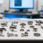
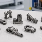
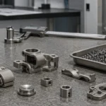
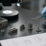
Quick answer: MIM feedstock affects part quality because it controls how metal powder and binder behave before injection molding, debinding, sintering, and final inspection. Stable feedstock supports consistent mold filling, green part strength, safe binder removal, predictable shrinkage, and repeatable dimensional control. Poor powder-binder dispersion, unstable solid loading, moisture, volatile content, rheology drift, or lot-to-lot …
Quick answer: MIM feedstock affects part quality because it controls how metal powder and binder behave before injection molding, debinding, sintering, and final inspection. Stable feedstock supports consistent mold filling, green part strength, safe binder removal, predictable shrinkage, and repeatable dimensional control. Poor powder-binder dispersion, unstable solid loading, moisture, volatile content, rheology drift, or lot-to-lot variation can later appear as short shots, cracks, voids, blistering, warpage, surface defects, or dimensional drift. For quality review, engineers should not only confirm that feedstock pellets can be molded. They should also evaluate powder consistency, binder behavior, pellet uniformity, rheology response, debinding safety, shrinkage behavior, and critical dimension stability.
Primary review focus
Feedstock quality, solid loading, rheology, binder behavior, and lot consistency.
Main quality risks
Short shots, cracks, voids, warpage, surface defects, and dimensional variation.
Project action
Review drawings, material requirements, critical dimensions, tolerance needs, and annual volume before tooling or production approval.
This article focuses on the technical logic behind that chain. It explains how powder characteristics, binder architecture, solid loading, compounding quality, and rheology shape part quality in real MIM production. It also shows how feedstock-related problems turn into actual defects, what engineers should watch during development, and what QA should verify before a feedstock batch or externally supplied feedstock pellet lot is accepted for production validation.
If you need the process-side background before reviewing quality risk, start with the MIM feedstock process guide. To understand MIM quality as a full system rather than as isolated process steps, this article also works well together with the metal injection molding overview, MIM process guide, and MIM materials guide.
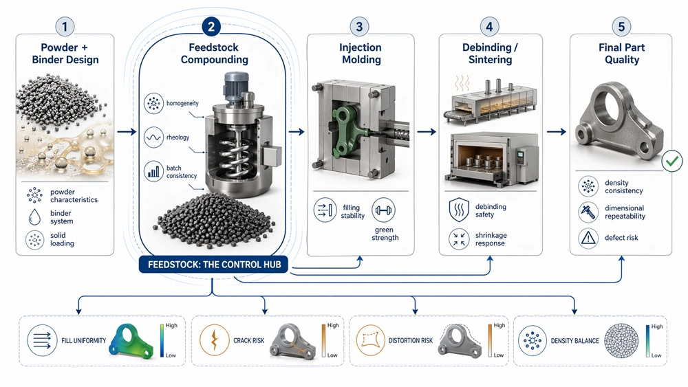
Core conclusion: Feedstock is not just a preparation step. It is the control bridge between powder-binder design and final MIM part quality.
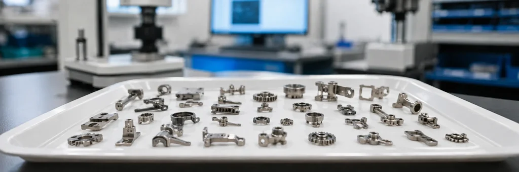
This figure shows why feedstock should not be treated as a minor upstream detail. The powder, binder, solid loading, and compounding stage do not stay isolated. They directly affect mold filling stability, green strength, debinding safety, shrinkage response, density consistency, and final dimensional control. If variation enters the process here, later stages usually spend their time compensating for it.
What Feedstock Really Controls in MIM
In MIM, feedstock is not just a preparation step. It is the stage where metal powder is turned into a moldable system that must perform well not only during injection, but also during handling, debinding, sintering, and final inspection. According to the Metal Injection Molding Association process overview, MIM feedstock is produced by mixing very fine metal powder with a multi-component binder and then granulating the material into pellets for molding. That description is correct, but in production the more important question is whether the feedstock creates a stable process window or forces every downstream stage to compensate for hidden variation.
A stable feedstock supports at least five quality outcomes at the same time: consistent cavity filling, sufficient green strength, safe binder removal, uniform shrinkage, and repeatable final density. Once one of those breaks down, the problem often changes form as it moves downstream. A short shot may first look like a tooling or pressure issue. A crack may first look like a debinding problem. Dimensional drift may first look like a furnace problem. In many cases, however, the real root cause begins inside the feedstock itself.
Key takeaway: feedstock quality is not only about making powder injectable. It is about building a stable bridge between powder behavior, molding performance, binder removal, shrinkage response, and final part consistency.
Feedstock Factors That Affect MIM Part Defects and Stability
A MIM feedstock is not only powder plus binder. It is a powder phase, a binder system, and the interface between them. Each part of that system has its own role, and final part quality depends on whether those roles remain compatible throughout the process chain.
| Feedstock factor | What changes in production | Possible MIM part quality issue |
|---|---|---|
| Powder particle size distribution | Changes packing behavior, binder demand, flow resistance, and sintering response. | Dimensional variation, surface roughness, density inconsistency, or unstable shrinkage. |
| Powder shape and surface condition | Affects friction, flow behavior, wetting, and contamination sensitivity. | Poor filling, local weak zones, surface defects, or abnormal sintering behavior. |
| Binder system balance | Controls moldability, green strength, backbone support, and binder removal behavior. | Green part damage, debinding cracks, blistering, distortion, or incomplete binder removal. |
| Solid loading | Controls viscosity, shrinkage amount, powder packing, and process window width. | Short shot, high injection pressure, warpage, shrinkage scatter, or unstable dimensions. |
| Powder-binder homogeneity | Determines whether the feedstock entering the mold is truly uniform. | Local density mismatch, voids, weak sections, and inconsistent sintering shrinkage. |
| Moisture and volatile control | Changes gas generation and flow stability during molding or debinding. | Bubbles, cracks, surface marks, internal voids, or debinding instability. |
| Lot-to-lot consistency | Changes the molding window and downstream shrinkage response between batches. | Batch-to-batch dimensional drift, unstable quality, and higher process adjustment cost. |
Powder characteristics
On the powder side, alloy selection is only the starting point. Particle size distribution affects packing behavior, binder demand, rheology, and sintering response. Particle shape affects friction, flow resistance, and how easily the material moves through thin or long-flow sections. Surface condition and contamination also matter. Fine powder usually supports better sintering activity and better detail reproduction, but it also increases surface area, which tends to raise binder demand and makes the feedstock more sensitive to flow instability. That is why the powder decision should be reviewed together with the expected molding window and the required part quality, not in isolation.
This logic is closely related to the broader material system. If you have not already reviewed the upstream alloy selection side, it is useful to compare this section with the MIM materials guide.
Binder architecture
The binder is also a system rather than a single ingredient. In practical MIM production, different binder components support different functions. Some improve flow during molding. Some provide backbone strength so the green part can be handled without damage. Others make binder removal possible under the selected debinding route. The MIMA process overview notes that binder selection is directly linked to debinding method, and that link is one of the most important engineering realities in MIM. A feedstock that fills the cavity well can still become a poor production choice if the binder system does not create a safe removal path for thick sections, local mass concentration, or uneven wall transitions.
That is also why feedstock work should not be separated from the downstream process chain. If your team is reviewing binder removal risk at the same time, it is worth reading this article together with the MIM debinding process guide and the debinding and sintering quality guide.
The powder-binder interface
The interface between powder and binder is where many hidden failures begin. If wetting is poor, if dispersion is incomplete, or if powder-binder separation develops during compounding, the material entering the mold is no longer truly uniform. The cavity may still appear to fill, but the feedstock is already carrying local variation. Later, that hidden variation shows up as local density mismatch, weak sections, shrinkage scatter, or dimensional instability.
Composite field scenario for engineering training: a common early-stage mistake is to approve a feedstock because trial molding looks acceptable from the outside. In actual production, the same feedstock may later show localized distortion after debinding or inconsistent shrinkage after sintering. The reason is often not visible on the molded surface. It may be a feedstock uniformity issue that created internal density variation before the part ever reached the furnace.
Why Solid Loading Is One of the Most Sensitive Feedstock Variables
MIM solid loading is often treated as a simple optimization target, but in practice it is one of the most sensitive variables in the feedstock stage. Higher powder loading can improve shrinkage control and reduce the amount of binder that must be removed. However, it also raises viscosity and can reduce the process window very quickly. Lower powder loading may make flow easier, but it often increases shrinkage and makes final dimensional control harder. There is no universal best value because the usable range depends on the powder system, binder system, part geometry, molding conditions, and debinding route.
A more useful engineering mindset is to separate critical powder loading from production operating loading. The critical value tells you where the feedstock begins to lose practical flow stability. The production value should usually sit in a safer window below that limit. In a published technical study, one Fe-based feedstock system used this type of critical loading and practical molding-window review. The lesson is not to copy a single number. The lesson is that the best production value is usually the most stable operating window, not the highest number that can be claimed.

Core conclusion: Solid loading should be selected for process stability, not for the highest possible value.
A feedstock with low loading may flow more easily, but it usually brings higher shrinkage and weaker dimensional control. A feedstock with very high loading may reduce shrinkage, but it often raises viscosity, narrows the molding window, and increases far-end fill risk. The most practical target is normally the stable operating window in between.
A common sourcing mistake happens when a team assumes that the highest powder loading must also mean the best feedstock. In real production, an aggressively loaded feedstock may become highly pressure-sensitive, difficult to fill in long-flow cavities, and more likely to create underpacked thin sections. The part may still mold, but the process becomes less forgiving and lot-to-lot stability becomes harder to maintain.
Composite field scenario for engineering training: one trial production program for a small structural part showed unstable fill at the far end of several thin features. The initial assumption was that the gate design needed rework. Gate changes helped only slightly. The deeper issue was that the feedstock was already operating close to the upper practical loading limit. The result was a narrow molding window and inconsistent end fill. Once the feedstock operating window was adjusted, the cavity filled more consistently without requiring a major tool redesign.
Why Mixing and Compounding Quality Matter More Than Many Teams Expect
Even a sensible feedstock design can fail if the compounding stage is not controlled well. A technical review of powder-binder mixture processing shows that feedstock quality is strongly affected by mixing time, mixing temperature, addition sequence, powder characteristics, binder formulation, shear rate, and powder loading. In other words, compounding is not just a preparation task. It is the stage where a theoretical formula either becomes a production-capable feedstock or remains only a lab recipe.
Mixing temperature affects whether the binder properly wets the powder and whether the blend reaches a stable internal structure. If the temperature is too low, wetting and dispersion remain incomplete. If it is too high, binder degradation, volatilization, or formulation drift may begin. Mixing time has the same two-sided risk. Too short, and agglomerates remain. Too long, and the thermal and shear history can damage the system or increase contamination risk. Addition sequence matters as well. If powder is added poorly or too aggressively, the blend may trap non-uniform regions that survive granulation and later show up as batch-to-batch inconsistency.
Compounding control also connects directly to molding stability, so it makes sense to view this section together with the guide on how injection molding affects part quality in MIM. If the feedstock batch is inconsistent, the molding team can only compensate so much with machine settings.
Composite field scenario for engineering training: in one development run, a precision part with a thicker center body and several thin end features showed unstable filling only at the far end. The first reaction was to blame the gate location. Further review showed that the feedstock batch had a narrower-than-normal viscosity window caused by inconsistent compounding. Once batch consistency improved, the molding window widened and the far-end filling problem was reduced without major geometry change.
Rheology Tells You Whether a Feedstock Is Really Ready for Production
In MIM, rheology is not a laboratory formality. It is one of the clearest indicators of whether a feedstock is truly ready for production. Public technical literature repeatedly links feedstock rheology to homogeneity, mold filling behavior, and part quality. In practical terms, rheology helps answer four questions. Does the material shear-thin in a useful way? Is it too temperature-sensitive? Is batch behavior repeatable? And does the material remain stable under realistic processing history?
A useful MIM feedstock normally shows shear-thinning behavior because the material needs to flow under injection shear but still recover enough structural stability after filling. One viscosity number is not enough. Engineers should review the full rheology behavior package: viscosity across a usable shear range, temperature sensitivity, repeatability between batches, and signs of separation or instability. In MIM projects where part dimensions are tight or long-flow sections are present, this review becomes especially important because small rheology drift can produce visible quality variation later.

Core conclusion: A production-ready MIM feedstock needs usable shear-thinning behavior, manageable temperature sensitivity, and repeatable batch response.
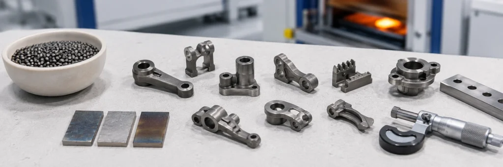
This figure helps explain why one viscosity value is not enough. Engineers should look at the overall rheology behavior: how viscosity changes with shear, how strongly the feedstock reacts to temperature, and whether different batches remain consistent across the expected molding range.
A frequent mistake is to treat good mold filling as proof that the rheology is acceptable. That is too narrow. A feedstock may fill well in a controlled short trial and still create later cracking, distortion, or dimensional scatter if its rheological behavior becomes unstable across temperature shifts, lot variation, or more complex mold conditions.
How Feedstock Problems Turn into Real MIM Defects
One of the most useful ways to understand feedstock is to stop treating it as an isolated step. Feedstock problems rarely stay inside the feedstock stage. They move downstream and change form. Poor dispersion may first create local filling imbalance, then green density variation, then shrinkage scatter, and finally dimensional inconsistency. Excessively high loading may first show up as weak far-end filling, then local density deficit, then sintering distortion. A mismatched binder system may first look acceptable in molding, then create trapped gases, blistering, cracking, or debinding-related distortion later.

Core conclusion: Most feedstock problems become visible later, which is why root-cause analysis should trace defects back through the full MIM chain.
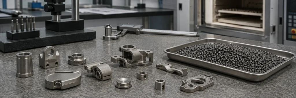
Poor dispersion, overloaded feedstock, binder mismatch, or batch inconsistency may not remain visible as material problems. They often reappear later as underfill, density mismatch, blistering, cracking, distortion, or dimensional drift. This figure helps users connect early material-stage variation to final product defects.
| Feedstock Issue | Early Process Symptom | Likely Downstream Result |
|---|---|---|
| Poor powder-binder dispersion | Local fill variation or unstable density distribution | Shrinkage scatter, dimensional inconsistency, weak zones |
| Solid loading too high | High viscosity, pressure sensitivity, incomplete far-end fill | Underpacked regions, distortion, unstable dimensions |
| Solid loading too low | Easy flow but larger binder volume | Higher shrinkage and weaker dimensional control |
| Binder system mismatched to debinding route | Green part may look acceptable after molding | Cracking, blistering, distortion during debinding |
| Weak batch consistency from compounding | Variable molding window between lots | Batch-to-batch dimensional drift and unstable quality |
Defect diagnosis table for feedstock-related review
| Observed defect | Possible feedstock-related cause | Other causes that should also be checked |
|---|---|---|
| Short shot or incomplete fine detail | High viscosity, poor flow behavior, excessive solid loading, or unstable rheology. | Gate size, venting, injection pressure, injection speed, mold temperature, and local wall thickness. |
| Cracks after debinding | Binder imbalance, moisture, poor powder-binder homogeneity, or unsafe binder removal behavior. | Heating rate, debinding atmosphere, section thickness, wall transition, and part support. |
| Blistering or internal voids | Volatile control issue, trapped gas, contamination, or local binder-rich area. | Debinding profile, venting, green part density, and furnace loading condition. |
| Warpage after sintering | Solid loading variation, local density mismatch, or uneven feedstock packing. | Sintering support, part geometry, wall thickness balance, setter design, and furnace profile. |
| Dimensional variation between batches | Lot-to-lot feedstock variation, viscosity drift, or inconsistent shrinkage response. | Tooling compensation, sintering profile, measurement method, and critical dimension strategy. |
| Surface roughness or black spots | Powder issue, contamination, binder residue, or poor dispersion. | Mold surface, injection condition, debinding completeness, sintering atmosphere, and secondary operations. |
Important boundary: not every MIM defect is caused by feedstock. Mold design, injection parameters, debinding profile, sintering support, material selection, and inspection method can create similar symptoms. Feedstock should be part of root-cause analysis, not the only explanation.
For broader troubleshooting, connect this review with the MIM quality control checklist, MIM inspection and testing capabilities, and MIM tolerance planning.
What QA Should Check Before Approving a Feedstock for Production
QA should not evaluate feedstock only by whether it can be molded into a visible part. Real approval should include material consistency, process behavior, and evidence from downstream response. For projects using externally supplied feedstock pellets, the review should include supplier-provided consistency information where available, plus internal validation through molding, debinding, sintering, and dimensional inspection response. This avoids implying that a feedstock formula is acceptable simply because the first molded samples look complete.
It is also useful to separate feedstock release data from true production-readiness evidence. A technically complete review often includes not only test results from the feedstock itself, but also practical downstream evidence: whether the batch debinds safely, whether shrinkage remains consistent, and whether critical part dimensions remain inside the intended control window. For standards and test-method context, the MPIF standards resources provide a useful reference point for material and testing discussions in powder metallurgy and MIM.
| QA checkpoint | Why it matters | Risk if ignored |
|---|---|---|
| Powder chemistry and contamination review | Confirms that the powder system matches the intended alloy and application risk. | Unexpected corrosion, magnetic behavior, strength issue, surface defect, or abnormal sintering response. |
| Particle size and morphology consistency | Affects packing, flow, binder demand, sintering activity, and surface condition. | Dimensional scatter, rough surface, unstable shrinkage, or density inconsistency. |
| Pellet uniformity and batch condition | Helps detect compounding or granulation variation before molding. | Unstable injection behavior, local underpacking, or batch-to-batch process drift. |
| Rheology behavior | Shows whether the feedstock has a usable molding window. | Short shots, pressure-sensitive filling, weld lines, or unstable fine-feature replication. |
| Moisture or volatile control | Reduces gas-related risks during molding and debinding. | Bubbles, voids, cracks, blistering, or surface marks. |
| Green part consistency | Connects feedstock quality to real molded part stability. | Hidden density variation, handling damage, and later shrinkage inconsistency. |
| Early debinding and sintering response | Confirms whether the feedstock can survive the full process route. | Late-stage cracking, distortion, dimensional drift, and delayed corrective action. |
What Designers and Buyers Often Miss About Feedstock
Designers often focus on geometry and assume feedstock is a materials issue that can be solved later. Buyers often compare feedstock decisions mainly by cost per kilogram. Both views are incomplete. Feedstock sensitivity changes with geometry. Long-flow features, uneven wall transitions, local mass concentration, and density-sensitive critical dimensions all increase the importance of feedstock design. At the same time, the lowest-cost feedstock is not always the lowest-risk production choice if it creates a narrow molding window, unstable debinding response, or higher rejection rates later.
That is why feedstock should be reviewed together with design, tooling, debinding, sintering, and inspection. If your team is deciding whether a part is truly MIM-friendly from the beginning, this section pairs well with the MIM design guidelines page and the MIM tolerance guide.
What to Provide for a Feedstock-Related Engineering Review
When a project has short shots, cracks, warpage, unstable dimensions, or unexplained surface defects, the review should not start with a simple price request. A useful MIM review needs the drawing, material, dimensions, tolerance targets, application conditions, and production background. This allows the engineering team to judge whether the issue is more likely related to feedstock, geometry, tooling, injection molding, debinding, sintering, or inspection strategy.
| Information to provide | Why it helps the review |
|---|---|
| 2D drawing and 3D CAD file | Allows review of wall thickness, long-flow areas, critical dimensions, ribs, holes, grooves, and local mass concentration. |
| Material requirement | Connects alloy selection to powder behavior, sintering response, corrosion, strength, magnetic, or wear requirements. |
| Critical dimensions and tolerances | Helps identify where shrinkage control and dimensional repeatability are most important. |
| Surface and cosmetic requirements | Helps judge powder, molding, debinding, sintering, and secondary operation risks. |
| Estimated annual volume | Supports process suitability, tooling investment, production planning, and cost structure review. |
| Current defect information, if available | Allows root-cause review of short shots, cracks, voids, warpage, surface defects, or dimensional drift. |
| Application environment | Clarifies whether corrosion, load, wear, magnetic response, temperature, or assembly fit must be prioritized. |
Request a Feedstock-Related MIM Quality Risk Review
Send your 2D drawing, 3D CAD file, material requirement, critical dimensions, tolerance needs, surface requirements, estimated annual volume, application background, and any existing defect information. XTMIM can review whether the quality risk is more likely connected to feedstock behavior, mold filling, debinding, sintering shrinkage, geometry, or inspection strategy before tooling, trial production, or production ramp-up decisions.
Standards and Technical References
This article uses external references only where they support the engineering topic. The MIMA process overview is useful for understanding the MIM feedstock, molding, debinding, and sintering route. The EPMA MIM overview provides additional context on powder-binder systems and MIM processing. The MPIF standards resources can support material and testing discussions, but project-specific acceptance criteria should always be confirmed against drawings, material requirements, inspection plans, and supplier process capability.
Final Engineering Takeaway
In MIM, feedstock quality is not only about making powder flow. It is about creating a stable bridge between powder characteristics, binder design, compounding quality, rheology, and the full downstream process chain. When feedstock is well designed and well controlled, molding becomes more stable, debinding becomes safer, shrinkage becomes more predictable, and final part quality becomes easier to hold. When feedstock control is weak, later processes spend their time compensating for variation that should never have entered the system in the first place.
Bottom line: if you want stable MIM quality, do not treat feedstock as a small upstream detail. It is one of the core process decisions that determines whether the entire part-quality chain will remain stable or become reactive.
Engineering review note: This article is prepared for B2B MIM project evaluation, including design feasibility, feedstock-related quality risk, debinding and sintering stability, dimensional repeatability, and drawing-based manufacturing review. Project-specific conclusions should be confirmed with actual drawings, material requirements, tolerances, inspection needs, and production volume.
FAQ
Does feedstock quality really affect the final MIM part that much?
Yes. Feedstock quality affects molding stability, green strength, debinding behavior, shrinkage consistency, density distribution, and final dimensional repeatability. Many late-stage defects begin with early feedstock variation.
Is higher solid loading always better in MIM feedstock?
No. Higher solid loading can reduce shrinkage and binder volume, but it also raises viscosity and narrows the molding window. The best production value is usually a stable operating window, not the highest possible loading.
Why can a feedstock mold well but still fail later?
Good filling does not automatically mean safe debinding or stable sintering. A feedstock may fill cleanly and still create cracking, blistering, warpage, or dimensional drift if the binder system, solid loading, and rheology are not balanced for the full process chain.
What feedstock issues can cause MIM part defects?
Common feedstock-related risks include poor powder-binder dispersion, unstable solid loading, excessive moisture, contamination, high viscosity, binder mismatch, and lot-to-lot variation. These issues may appear later as short shots, cracks, voids, surface defects, warpage, or dimensional variation.
What should QA check before releasing a feedstock batch?
QA should review powder consistency, contamination risk, pellet uniformity, rheology behavior, moisture or volatile control, and batch traceability. It should also check downstream evidence such as green density consistency, molding repeatability, shrinkage stability, and early distortion signals.
What information should buyers provide for feedstock-related MIM review?
Buyers should provide a 2D drawing, 3D CAD file, material requirement, critical dimensions, tolerance needs, surface requirements, estimated annual volume, application environment, and any existing defect information. This helps the engineering team review whether feedstock, geometry, molding, debinding, sintering, or inspection strategy may be driving the risk.