POWDER INJECTION MOLDING Powder injection molding (PIM) is a family of manufacturing processes used to produce complex components from fine metal, ceramic, and certain specialized powder materials. It combines injection molding with powder processing: powder is mixed with a temporary binder, molded into the required shape, debound, and sintered to develop the final component's material …
POWDER INJECTION MOLDING
Powder injection molding (PIM) is a family of manufacturing processes used to produce complex components from fine metal, ceramic, and certain specialized powder materials. It combines injection molding with powder processing: powder is mixed with a temporary binder, molded into the required shape, debound, and sintered to develop the final component’s material properties.
PIM primarily includes metal injection molding (MIM) and ceramic injection molding (CIM). Cemented carbide injection molding (CCIM) is also recognized as a specialized route. PIM is not a third alternative to MIM and CIM: it is the umbrella term for their shared forming and sintering principles.
A molded shape is only the starting point. A PIM component must also survive binder removal and sinter to the specified dimensions and material properties.
What Is Powder Injection Molding (PIM)?
Powder injection molding is a powder-based forming technology that combines the geometric flexibility of injection molding with the material characteristics obtained through sintering. It is a manufacturing process family, not the name of one particular metal or ceramic material.
In conventional plastic injection molding, the polymer is the finished part’s main material. PIM works differently. Fine material powder is mixed with a temporary binder to create an injectable feedstock. The binder enables shaping and holds the newly molded component together, but is later removed. The powder particles form the final material structure during sintering.
PIM uses injection molding to establish geometry; debinding and sintering then transform the molded powder structure into a functional component. The exact material properties and process conditions depend on the powder system selected.
PIM is related to conventional powder metallurgy but differs in the forming method. Traditional press-and-sinter powder metallurgy generally compacts powder in a rigid die. PIM injects a powder–binder mixture into a mold cavity, enabling certain three-dimensional features that are difficult to obtain by uniaxial compaction. Both approaches have their own geometry and tooling constraints.
PIM terminology: The abbreviation PIM also appears in unrelated industries. In manufacturing specifications, Powder Injection Molding (PIM) identifies the powder-based process; powder injection moulding is its British spelling. MIM refers specifically to the metal route within this family. For the broader process context, see related manufacturing processes.
What Are the Main Types of Powder Injection Molding?
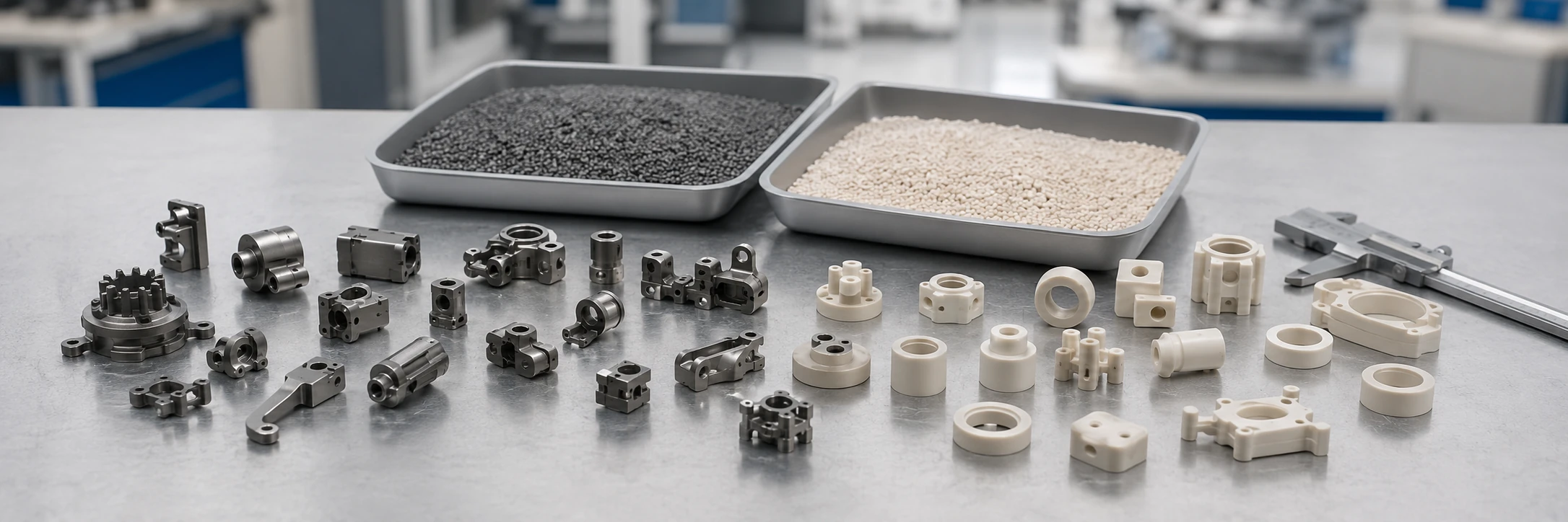
PIM is classified chiefly by the powder material being shaped. MIM and CIM are the two principal material routes. Certain specialized systems, including cemented carbides, are also processed by PIM and may be classified separately in industry education.
Metal Injection Molding (MIM)
Metal injection molding uses metal powder mixed with an organic binder to produce complex metal components through molding, debinding, and sintering. Common material families include stainless steels, low-alloy steels, precipitation-hardening stainless steels, and selected other metal alloys.
For example, 316L stainless steel may be considered where corrosion resistance is important, while 17-4 PH stainless steel may be appropriate where higher strength is required after validated processing and heat treatment. The selected alloy and manufacturing route determine achievable properties.
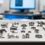
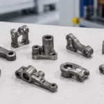
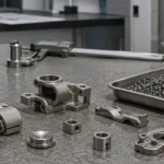
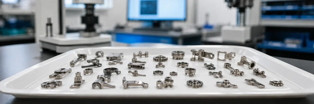
MIM is used for small, intricate metal parts such as mechanical levers, latches, miniature structural components, and precision hardware. It combines complex geometry with the functional behavior of a specific metallic material. See the detailed metal injection molding process for its metal-specific manufacturing controls.
Ceramic Injection Molding (CIM)
Ceramic injection molding uses ceramic powder and a temporary binder system to manufacture technical ceramic components. Common examples include alumina (Al₂O₃) and zirconia (ZrO₂); other ceramic materials may be used when compatible feedstocks and processing routes are available.
CIM is relevant when the required function comes from a particular technical ceramic. Alumina is widely considered for electrical insulation and certain wear-resistant uses. Zirconia can provide hardness and wear resistance with relatively high fracture toughness for a ceramic. No single set of properties applies to every ceramic grade.
Representative parts include ceramic insulating supports, sleeves, guides, and selected wear-resistant components. Their geometry, handling requirements, sintering response, and risk of brittle damage must be assessed for the chosen material. The ceramic injection molding guide covers the ceramic-specific design and processing requirements.
Cemented Carbide Injection Molding (CCIM)
Cemented carbide injection molding is a specialized PIM route used for complex hardmetal components. A typical material system is tungsten carbide–cobalt (WC–Co), in which hard carbide particles are bonded by a metallic phase.
Two different binders must not be confused: the temporary organic binder makes the powder mixture injectable and is removed in processing; the metallic binder phase, such as cobalt, remains in the finished cemented carbide. Some CCIM parts benefit from forming complex wear-resistant geometry before final densification, reducing otherwise difficult hardmetal machining.
Industrial classifications are not completely uniform: some place cemented carbides within the broader MIM field, while other technical resources discuss CCIM separately. It is an established specialized PIM application, not necessarily a universal third major category. For more on the material itself, see cemented carbides.
Other specific cermet and composite powder formulations can also be injection molded where a suitable feedstock and sintering system have been developed. Terms such as micro-PIM and low-pressure PIM refer to component scale or processing approach and should not be mixed with these material categories.
| Route | Typical powder materials | Finished component | Representative use |
|---|---|---|---|
| MIM | Stainless steel, low-alloy steel, selected metal alloys | Sintered metal part | Small mechanisms and precision metal hardware |
| CIM | Alumina, zirconia, selected technical ceramics | Sintered technical ceramic part | Insulators, sleeves, guides and wear components |
| CCIM | WC–Co and other appropriate cemented carbides | Cemented carbide part | Specialized complex wear parts and tool inserts |
CCIM is shown as a specialized route; classification conventions vary across industry references.
Although the resulting parts differ in material and performance, these routes are linked by a shared approach: forming powder-loaded feedstock in a mold, removing the temporary binder, and sintering the molded structure.
How Does Powder Injection Molding Work?
The PIM manufacturing sequence transforms a moldable powder mixture into a sintered material component. Each stage has a different purpose, and errors made early can remain visible after sintering.
- STEP 01Prepare feedstockPowder + temporary binder
- STEP 02Injection moldForm the green part
- STEP 03DebindRemove binder in stages
- STEP 04SinterBond particles; shrink
- STEP 05Inspect / finishVerify required properties
The final inspection checks dimensions and material requirements. Machining or other finishing is added only where necessary; binder-removal and sintering conditions depend on the feedstock system.
Powder and Binder Feedstock Preparation
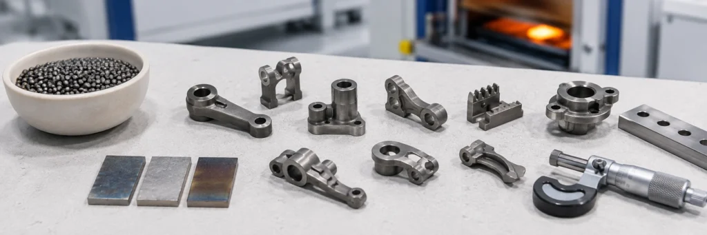
The process begins by combining fine powder with a binder formulation, often including polymers, waxes, or processing additives. The powder forms the principal material of the finished component; the binder provides flowability during molding and enough initial strength for green-part handling.
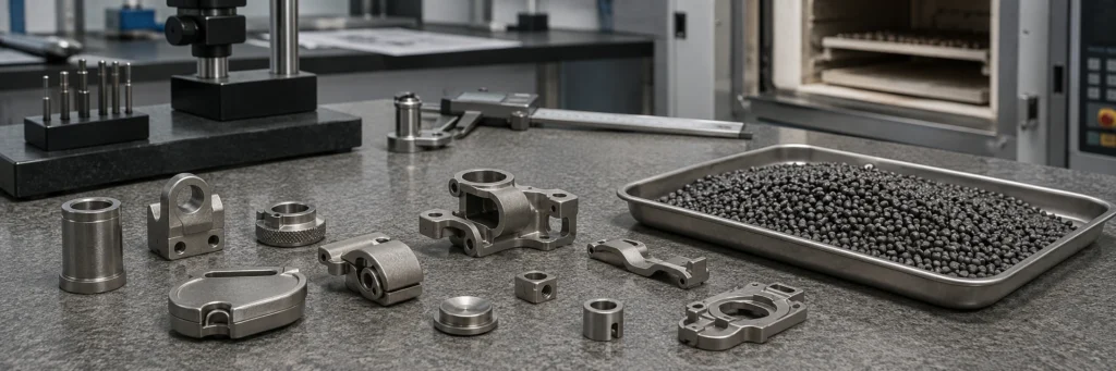
The mixture is known as feedstock and is often prepared as granules or pellets. To fill the mold reliably, it must flow under suitable conditions while maintaining a reasonably uniform powder distribution. Powder loading, particle size and shape, surface chemistry, binder compatibility, and mixing uniformity affect this behavior.
If the feedstock lacks sufficient flowability, thin or distant features may fail to fill. Poor powder distribution can also lead to uneven density and subsequent dimensional variation. Feedstock preparation is therefore not simply a matter of mixing metal or ceramic powder with plastic.
Injection Molding and Green Part Formation
Prepared feedstock is heated under appropriate processing conditions and injected into the mold cavity. The mold creates the initial external profile and those internal features that can be formed and released using the tool design.
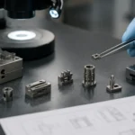
After cooling and ejection, the component is called a green part. It resembles the intended component but still contains the temporary binder, and its final material structure has not yet developed. It must tolerate ejection, handling, and transfer without damage.
The green geometry is generally larger than the final sintered part because later densification produces shrinkage. The required compensation depends on feedstock, material, tooling, and processing conditions, not on one universal PIM scaling factor.
Debinding: Removing the Binder
Debinding removes the temporary binder while preserving the shape of the packed powder. Solvent extraction, catalytic decomposition, thermal treatment, or combined methods may be used depending on the feedstock system.
In some routes, one binder component is removed first and a residual component holds the powder together until a later thermal step. A substantially debound intermediate is often called a brown part, but the terminology and distinct intermediate stages are not identical across every PIM system.
Binder removal must be controlled. Thick areas or long removal paths can create internal pressure or uneven binder loss, causing blistering, distortion, or cracking. Successful debinding means preserving the molded powder geometry for sintering, not merely removing as much binder as quickly as possible.
Cracking at a thick-to-thin transition during debinding (illustrative case)
A green part with a thick hub joined to a thin arm looks intact after molding, yet fine cracks develop near the transition during binder removal.
Binder can leave the thick section more slowly than the thin one. The difference may create local pressure or weaken the powder structure, although molding defects or handling damage can produce similar symptoms.
Inspect parts after molding and at successive debinding stages, and record when and where cracks first appear. Damage recurring at the same transition supports investigating the binder-removal path, but it does not establish a single cause.
Review wall-thickness transitions, debinding conditions, green-part support and handling, then validate any targeted change before altering the mold.
Sintering, Shrinkage and Final Part Properties
During sintering, heat drives particle bonding, microstructural change, and often pore reduction and densification. Some materials sinter predominantly in the solid state; others involve a liquid phase during part of the cycle.
The component usually shrinks as the powder structure consolidates. Wall thickness, powder distribution, geometry, furnace loading, support conditions, thermal history, and the selected atmosphere influence how evenly this occurs. When different regions shrink at different rates, enlarging the mold by one nominal factor will not, by itself, prevent distortion.
Directional warpage after sintering (illustrative case)
A small molded lever appears straight before sintering but bends consistently in one direction after firing.
Uneven powder packing, section thickness, gravity, contact with the sintering support or local thermal conditions can contribute to this deformation. The final shape alone does not identify the dominant cause.
Compare dimensions before and after debinding and after sintering, then check the direction of bending across parts and furnace loads. A recurring orientation can point toward support or loading conditions; distortion concentrated around a feature may call for a closer review of geometry and green density.
Any change to the support, loading orientation, section transition or molding conditions should be verified on sintered samples before the tooling compensation is revised.
Sintering determines the final material structure and affects density, strength, wear response, and other functional properties. The goal is to meet the specified material and dimensional requirements, not to assume every PIM route produces perfectly full density.
Finished components are inspected. Depending on the project, some may also require machining, grinding, polishing, heat treatment, or surface processing. These operations are selected for a specific functional requirement rather than imposed on every PIM component.
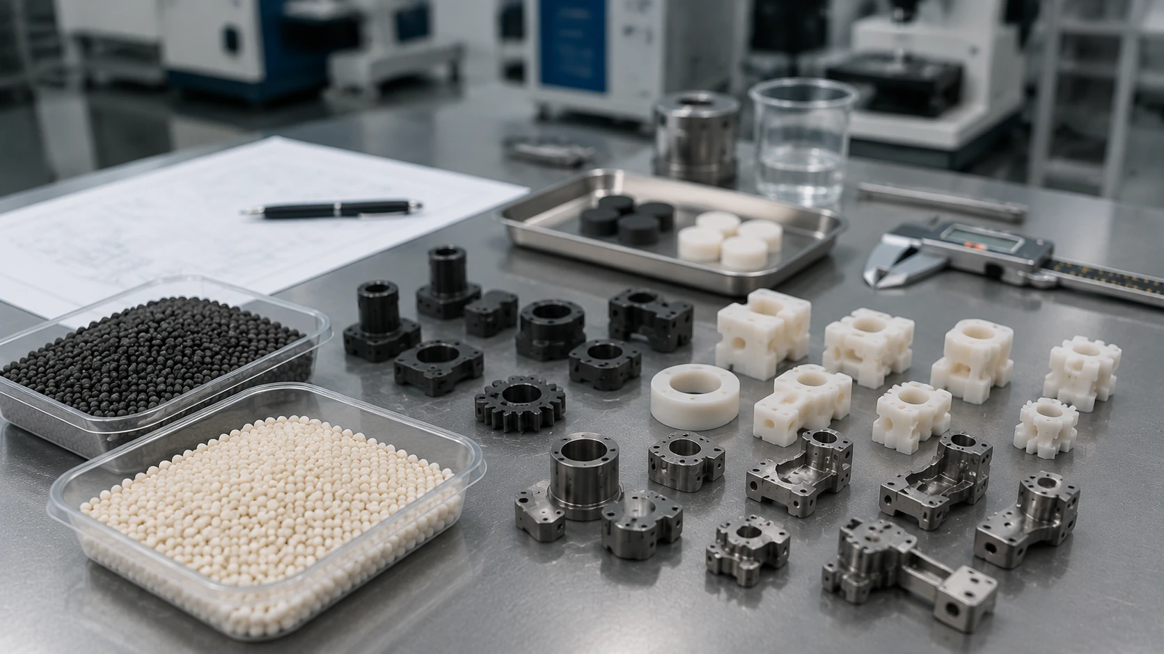
Shared equipment does not mean interchangeable process conditions. Metal, ceramic and cemented carbide feedstocks can require different binder-removal methods, furnace atmospheres, thermal cycles and contamination controls, even when the same categories of machines are used.
What Are the Main Advantages of Powder Injection Molding?
PIM combines molded geometric complexity with the properties of a selected powder material. These benefits matter when the geometry and production requirements justify tooling, debinding, and sintering.
Complex Geometries and Near-Net-Shape Manufacturing
PIM can form certain complex three-dimensional features directly in the mold, including recesses, curved profiles, integrated mounting details, and multiple external surfaces. When these features would otherwise require several machining setups, a validated molded route may reduce material-removal operations.
This is known as near-net-shape manufacturing: a substantial portion of the part’s final geometry is created before finishing. It does not guarantee that every bore, mating interface, sealing surface, or critical dimension will meet its final specification without secondary work.
The advantage is strongest when complexity justifies mold production but the shape still permits filling, mold release, debinding, and sintering.
Functional Material Properties in Powder-Based Parts
PIM can produce components from material systems with properties not available from ordinary molded plastics. For example, a selected stainless steel may provide metallic mechanical behavior and corrosion resistance, a selected alumina grade may provide electrical insulation, and a cemented carbide may provide resistance to abrasive wear.
Those properties belong to the chosen material and validated processing conditions, not to PIM as a universal material. The manufacturing value is the ability to combine suitable powder-material performance with complex molded geometry.
Repeatable Manufacturing at Production Volumes
After tooling and process validation, a mold can repeatedly form components with the intended geometry. Multiple cavities may improve productivity where design, filling balance, debinding, and sintering stability allow.
Economic benefits depend on total manufacturing cost, not the molding cycle alone. Powder and feedstock cost, tooling, debinding and sintering, scrap and yield, inspection, required finishing, and expected production volume all matter.
PIM is not automatically cheaper than CNC, pressing, or other manufacturing methods; it becomes attractive when the part design and batch or lifetime volume can justify the development and tooling investment.
Where Is Powder Injection Molding Used?
PIM is used when a component needs both a suitable powder-based material and geometric features that benefit from injection molding. The relevant process depends on the final part’s required properties, not simply on the industry it serves.
In consumer electronics and precision mechanisms, small metal latches, levers, connectors, or similar components may benefit from MIM when several features can be consolidated into one molded shape. Industrial and automotive equipment can also use MIM for suitably complex mechanisms and small structural parts.
For a small latch, molding recesses and mounting features together may eliminate separate machining setups. That advantage matters only if the features can be filled, released from the mold and carried through debinding and sintering without losing their required geometry.
Technical ceramic parts made by CIM may include electrically insulating supports, sleeves, guides, or selected wear-resistant components. Their applications are driven by the material’s electrical, thermal, wear, chemical, and mechanical requirements.
Specialized cemented carbide systems may be used for complex wear-resistant parts and tool-related components where shaping the geometry before final densification could reduce difficult grinding or machining.
| Representative component | Why PIM may help | Material route | Possible industry |
|---|---|---|---|
| Small stainless-steel latch or lever | Complex profile with functional metal properties | MIM | Precision mechanisms, wearables, electronic hardware |
| Miniature metal actuator component | Integrated geometry and repeatable molded production | MIM | Industrial and automotive equipment |
| Ceramic insulating support | Electrical insulation and defined molded geometry | CIM | Electrical or electronic assemblies |
| Ceramic guide or wear element | Wear resistance and material-specific surface performance | CIM | Industrial machinery |
| Complex hardmetal wear part | Hard wear-resistant material with difficult finishing geometry | CCIM | Industrial tooling |
Illustrative component examples, not XTMIM production case studies. The actual material, geometry and manufacturing route require verification.
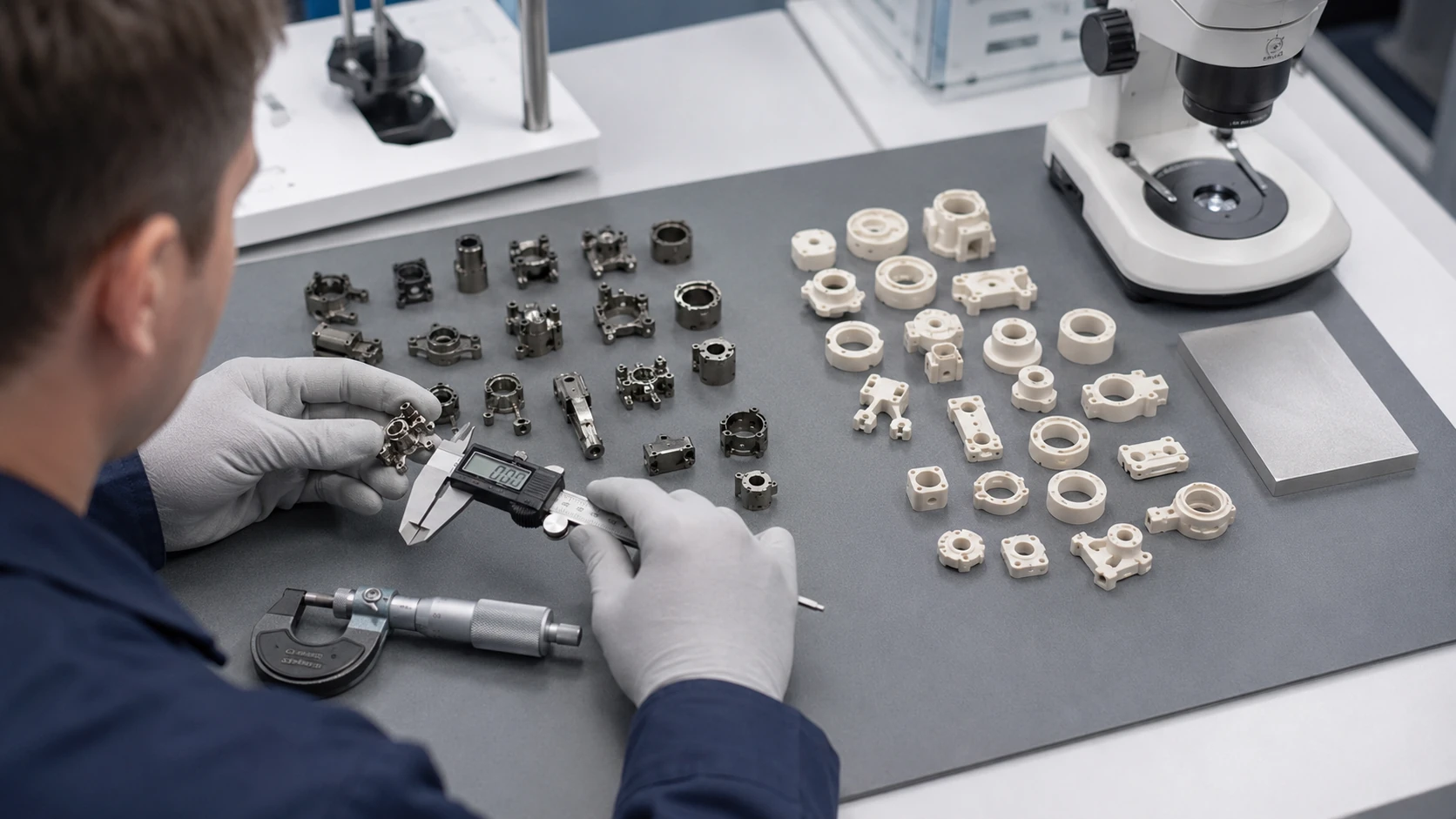
Two different reasons to use PIM (illustrative examples)
Stainless-steel latch. When a compact latch combines several molded features with corrosion and strength requirements, MIM may reduce separate machining operations at repeat production volumes. Critical holes or mating faces still need an as-sintered capability check or a finishing allowance.
Ceramic insulating support. CIM may be useful when an insulating component has a shape that would be difficult to grind from dense ceramic. The ceramic grade must provide the required electrical and mechanical behavior, while the geometry must survive debinding, sintering and handling without unacceptable distortion or chipping.
A similar shape can be made from different materials for different functions. Conversely, not every stainless-steel, ceramic, or hardmetal component is made using PIM: pressing, machining, casting, extrusion, and other methods may be better suited to the actual requirements.
What Are the Limitations of Powder Injection Molding?
PIM can form intricate functional components, but a part must be compatible with the entire molding–debinding–sintering chain. Moldability alone does not establish final manufacturability.
Tooling and Geometry Constraints
PIM requires a mold that the powder-loaded feedstock can fill and from which the green part can be released without unacceptable damage. Parting lines, draft, venting, gate placement, ejection, undercuts, and localized wall geometry therefore matter.
Some features require slides, cores, or additional tooling mechanisms; others may need redesign or secondary machining. Abrasive powders can create additional tooling wear considerations. Sudden changes from thick to thin walls may also affect molding and downstream binder removal or sintering.
Debinding, Sintering and Shrinkage Risks
During debinding, the part must preserve its geometry while temporary binder is removed. During sintering, thermal processing and dimensional changes must remain controlled. Typical risks include cracking, blistering, slumping, uneven shrinkage, warpage, and residual porosity.
The causes vary by material system, powder distribution, wall thickness, unsupported features, furnace conditions, and supporting fixtures. A thin feature may mold successfully yet distort after its temporary binder is removed. A thick section may require a different binder-removal schedule from a uniformly thin component.
A crack first seen after debinding calls for a different investigation from warpage that develops only during sintering. Inspecting parts at each stage, checking green-part uniformity and reviewing support contact can narrow the causes; tighter mold machining alone cannot prevent both failures.
Dimensional Accuracy and Secondary Processing
Since PIM parts shrink between molding and final sintering, the tooling must compensate for expected dimensional change. Shrinkage is influenced by the actual material system and manufacturing conditions, so no universal scaling factor or as-sintered tolerance applies to all PIM components.
Some precision bores, mating faces, sealing surfaces, or critical dimensions may require machining, grinding, polishing, or other post-sintering operations. Ceramic finishing additionally requires appropriate protection against chipping and brittle damage.
The drawing should distinguish dimensions expected to meet specification as sintered from those assigned to machining or grinding. This helps estimate finishing cost and define how each critical feature will be inspected.
When May PIM Be Less Suitable?
PIM may offer limited advantage for very simple geometry, very low quantity, designs that change frequently, unusually large or thick components, features prone to handling and sintering damage, or products requiring extensive precision finishing after molding.
For example, a simple cylindrical pin may be more practical to machine than to develop PIM tooling for. A prototype that is still being redesigned may also be better served by machining or another flexible process until the geometry is stable.
A moldable part that may not justify PIM tooling (illustrative case)
Consider a simple component with uncertain annual demand and several tight-tolerance interfaces. Its shape may be easy to mold, but the critical features would still require considerable machining after sintering.
Separate the geometry that PIM could produce to specification from the geometry that would still need machining, grinding and inspection. Then spread tooling and process-development costs over a realistic lifetime production volume, not just the injection cycle time.
If much of the work remains in secondary operations or the design is still changing, CNC machining or another flexible process may be the more economical route until requirements stabilize.
These are reasons to compare manufacturing routes, not absolute exclusions. Geometry, material requirements, expected volume and total finishing cost still determine the practical choice.
A moldable shape is not yet a viable PIM part. The component must survive binder removal and sintering, meet the required dimensions and material properties, and remain economical at the intended production volume.
Key Takeaways: Understanding Powder Injection Molding
PIM combines two manufacturing requirements: the powder-binder mixture must form the required geometry, and the molded structure must survive debinding and sintering to meet final material and dimensional specifications.
- PIM is the umbrella term. MIM and CIM are its main metal and ceramic routes; CCIM is a recognized specialized cemented-carbide application.
- Its stages are connected. Feedstock quality, molding, debinding, and sintering all affect the finished part.
- Material systems determine final properties. Metal, technical ceramic, and hardmetal parts need distinct validated conditions.
- Its value depends on part and volume. Complex near-net-shape geometry and repeatable production are useful when the full process is feasible.
- Its limits are real. Mold release, shrinkage, damage risks, precision requirements, finishing, and tooling economics require evaluation.
PIM describes a manufacturing method, not a universal material. The required properties first determine the powder system; geometry, binder removal, sintering and production volume then determine whether the route is practical. For a more detailed comparison of its main material routes, see MIM vs CIM. Metal-specific manufacturing requirements are covered under metal injection molding.
Evaluating a complex metal component? A drawing review can identify tooling, shrinkage, finishing and inspection questions that need to be resolved before a MIM process is selected.
Frequently Asked Questions
Is powder injection molding the same as 3D printing?
No. PIM uses a mold, temporary binder removal, and sintering to make repeated molded parts from powder feedstock. Powder-based 3D printing builds a part layer by layer and may use different binding or melting mechanisms. Both can use powder materials, but their production logic, tooling needs, and economic advantages are different.
Can any metal or ceramic powder be used for PIM?
Not automatically. A powder must be compatible with a validated feedstock system, binder-removal route, sintering method, and final property target. Material availability in PIM depends on more than the powder chemistry alone.
Do PIM parts always need secondary machining?
No. PIM is often used for near-net-shape manufacturing, so many features may be created directly by molding and sintering. However, critical bores, sealing faces, mating features, or tight-tolerance surfaces may still need machining, grinding, polishing, or other finishing operations.
How can engineers judge whether a part is a good PIM candidate?
A strong candidate typically combines a suitable powder material, geometry that benefits from molded complexity, and production volume that can justify tooling and process validation. The part must also remain manufacturable through molding, debinding, sintering, inspection, and any required finishing steps.