CNC-to-MIM Drawing & DFM Questions Quick answer: Mark the functional dimensions, datum features, and geometric controls on the existing CNC drawing. For each characteristic, record its purpose, approved tolerance, possible MIM shrinkage or distortion risk, proposed as-sintered or secondary-operation route, and final inspection method. A tight CNC tolerance is not automatically function-critical, but it remains …
CNC-to-MIM Drawing & DFM Questions
Quick answer: Mark the functional dimensions, datum features, and geometric controls on the existing CNC drawing. For each characteristic, record its purpose, approved tolerance, possible MIM shrinkage or distortion risk, proposed as-sintered or secondary-operation route, and final inspection method. A tight CNC tolerance is not automatically function-critical, but it remains a drawing requirement until the design owner approves any change. Keep dimensions without credible manufacturing evidence or an agreed acceptance method open for validation before tooling.

Stage 1 · Understand the problem
Why CNC Drawing Tolerances Need Review Before MIM Tooling
An existing CNC drawing is a valid statement of the product's current requirements, but it may also reflect the way the part was machined and inspected. A tight dimension might be essential to an assembled mechanism; it might instead have been easy to hold within the original machining setup. The drawing alone does not always tell a new manufacturing supplier which situation applies.
CNC machining removes material and can finish selected features in successive operations using defined fixtures and toolpaths. MIM starts with a molded green part, followed by debinding and sintering. The final part changes size during sintering; its dimensional outcome depends on feedstock and material, section geometry, tooling compensation, support, process control, and any finishing operations. A reference surface created by machining may not be present in the same form on an as-sintered part.
The drawing review must distinguish three decisions: which dimensions protect the product's function, which are sensitive to the proposed MIM process, and how each requirement will be manufactured and verified. Existing tolerances do not become looser merely because the process changes. Nor does every close-tolerance feature necessarily require machining after sintering.
A design requirement and a manufacturing route are different decisions. A customer-approved hole-position tolerance can remain unchanged when the part moves to MIM; the supplier then needs a manufacturing and inspection route that can meet it. A dimension associated with the original CNC setup may merit a design review, but it cannot be changed without approval from the design owner. Keep proposed manufacturing changes separate from authorized drawing revisions.
Function risk
A pin hole, locating face, or sliding interface can fail in the assembly even when the rest of the part looks acceptable.
Tooling risk
If the feature's purpose is unclear, shrinkage compensation and secondary-process allowances may be defined on the wrong assumptions.
Acceptance risk
A CNC prototype and an MIM production part may be measured against different setup references unless the datum and inspection plan are agreed.
If the manufacturing process has not yet been selected, the MIM vs CNC machining comparison addresses the wider process trade-offs. The dimensional review below applies once a CNC-to-MIM route is being evaluated.
Drawing baseline: Confirm the drawing revision and identify the dimensions that control assembly, movement, alignment, sealing, or acceptance before assessing MIM capability.
Stage 2 · Identify and classify
Which Dimensions on the CNC Drawing Are Critical to Function?
A critical dimension is one that controls a required outcome, not simply one with the smallest tolerance value. Start with how the component fits into its assembly. Ask what would happen if a feature were at the upper or lower limit, or if its position or orientation changed. A functional dimension can govern clearance, interference, alignment, load transfer, sealing, sliding motion, or an acceptance check required by the customer.
When the functional intent is not obvious, trace a simple cause-and-effect chain: feature → mating condition → plausible out-of-limit behavior → required acceptance criterion. For example, a clearance hole can tolerate some diameter variation yet still require tight positional control because the mating pin must enter without side-loading. Conversely, a visually precise edge is not automatically function-critical unless its envelope, contact, handling or appearance requirement establishes a limit. Record the reason rather than merely highlighting every small tolerance on the PDF.
Consider a hypothetical small industrial locating component being converted from CNC machining to MIM. Its pin hole (F1), locating face (F2), sliding contact surface (F3), and non-contact perimeter (G1) will be examined through the same drawing-review steps. The geometry and feature IDs are schematic; they do not represent a customer's approved drawing or measured XTMIM production results.
Assembly Fits and Mating Dimensions
Identify holes, pin seats, slots, shaft interfaces, screw clearances, and other features that physically mate with another part. Record the mating component and the intended behavior: free clearance, controlled location, interference, rotation, or load transfer. A hole's diameter and its position can have different functional consequences; reviewing only one of them can miss an assembly failure.
At F1, the pin hole, check the specified fit with the pin and the hole's position relative to the mating assembly. Knowing the nominal diameter alone will not establish whether the pin aligns correctly once the component is seated.
Datum and Location Relationships
Separate a drawing's designated datum features from surfaces used only to hold the part during CNC machining. Functional datums establish how the component is located in the real assembly. Geometric controls such as position, perpendicularity, flatness, or profile must be interpreted relative to the applicable datum scheme when the drawing specifies one.
F2 is the locating face. If the assembly seats against F2, its flatness and orientation relative to F1 can determine whether the pin aligns, even when the overall part width is within tolerance. Confirm that functional relationship before choosing the datum and inspection scheme.
Functional Motion and Contact Surfaces
Review sliding, sealing, rotating, and wear-contact interfaces as functional surfaces even when the numerical dimensional tolerance appears ordinary. In these areas, surface texture, contact geometry, material condition, or finishing can matter as much as one linear dimension. Thread features also need a functional review for engagement and fastening, but not every molded hole or clearance slot should automatically be labeled precision-critical.
F3 is the sliding contact surface. It may need a surface-condition requirement and a functional motion check, not just a width measurement. By contrast, G1 is the non-contact perimeter, a candidate for review as general geometry only if its clearance, safety, appearance, or other product requirement does not make it critical.
| Example feature | What it controls | Question to ask | Initial classification |
|---|---|---|---|
| F1 · Pin hole | Pin fit and assembly alignment | What mates with the hole, and which position relationship matters? | Function-critical; assess diameter and location separately |
| F2 · Locating face | Seating, orientation, and datum relationships | Does the assembly seat or locate on this surface? | Function-critical datum candidate |
| F3 · Sliding face | Motion and contact behavior | What movement, texture, and wear behavior must be maintained? | Function-critical surface |
| G1 · Outer contour | Potentially appearance or general envelope | Does it affect clearance, assembly, handling, or other requirements? | Review before classifying as noncritical |

Functional feature register: Record each feature ID, its mating or functional purpose, and any important size or geometric relationship. Use that register to examine the original CNC tolerances.
Stage 2 · Review the existing drawing requirements
Which CNC Tolerances Must Be Preserved or Reassessed?
Function-based classification does not authorize a supplier to change the customer's drawing. It identifies the engineering reason behind each requirement and flags where clarification may be useful. The design owner remains responsible for approving any revised tolerance, datum scheme, surface requirement, or drawing note.
Requirements That Must Protect Part Function
Preserve approved constraints that define necessary assembly fit, position, alignment, motion, sealing, loading, or interchangeability. Keep the relevant geometric controls, material and surface conditions, and acceptance notes together with the feature they govern. If the drawing contains a position requirement on F1 relative to the locating face F2, treating the hole diameter alone as the requirement would be an incomplete transfer.
A tolerance may need to be retained even when it will be expensive to manufacture. That cost question belongs in the MIM control-route review, not in an informal decision to weaken the product's functional requirement.
CNC-Inherited Tolerances That Need Design Review
Look for broadly tight default tolerance blocks, dimensions tied to CNC setup conveniences, or non-contact profiles where no functional reason has yet been recorded. Such features are candidates for clarification, not automatically safe dimensions to relax. Check for hidden stack-up effects, assembly clearance, cosmetic specifications, tooling interfaces, and downstream operations before proposing a change.
For G1, a non-contact perimeter might be suitable for ordinary process-controlled geometry. Yet the design owner should first confirm that it does not control envelope clearance or another hidden requirement. For a threaded feature, clarify engagement and strength requirements; do not assume that the thread or its pilot hole can be molded or tapped without review.
G1 example · A non-contact edge may still control clearance
A CNC drawing specifies a tightly controlled perimeter, although G1 appears to have no direct mating contact. The contour may still determine assembly-envelope clearance or whether the finished part fits a downstream fixture. Check the nearest surrounding geometry and minimum clearance in the final treated condition with the design owner. If the original tolerance has no necessary functional role, request a documented design revision; otherwise retain it and evaluate the proposed MIM route against that requirement.
| Review status | Use when | Engineering action | Who confirms? |
|---|---|---|---|
| Preserve | Requirement protects an approved function or interface | Transfer the specified requirement into the MIM capability and verification review | Design owner confirms requirement; supplier evaluates route |
| Reassess | A tolerance appears inherited from CNC, with no documented function | Ask whether an alternate tolerance or design approach is acceptable | Design owner approves or rejects any revision |
| Clarify | Missing mating context, datum intent, final condition, or test criteria | Obtain drawings, assembly information, or acceptance clarification | Customer engineering and quality, with supplier input |
Original drawing requirements remain in force
General tolerances still apply until the customer approves a revised specification. A supplier may flag an unnecessarily restrictive tolerance or propose different limits for functional and nonfunctional features, but cannot treat the existing CNC drawing as superseded without approval.
Where the dimensional assessment also identifies material, geometry, or mold-design issues, check them against the MIM design review before tooling.
Tolerance disposition: Mark requirements as preserved, awaiting design approval, or requiring clarification. Only approved requirements and explicitly identified open items should enter the manufacturing-capability comparison.
Stage 3 · Evaluate risk and capability
Can MIM Meet the Critical Dimensional Requirements?
A feature being function-critical does not automatically mean it will be difficult to make by MIM. Equally, a feature that looks noncritical can make nearby functional dimensions unstable if its geometry creates uneven shrinkage or distortion. Compare the required characteristic with the proposed manufacturing route rather than comparing CNC and MIM as if each had one universal tolerance number.
Shrinkage, Geometry, and Distortion Risks
MIM tooling is designed around the expected dimensional change during debinding and sintering, but local geometry and process conditions affect how consistently the part reaches its final shape. Thick-to-thin section transitions can create unequal shrinkage and bending; heavy local sections and long unsupported areas can also affect nearby feature positions. Review these features during DFM because a nominally correct overall shrinkage allowance may still leave a functional hole or locating face out of tolerance.
Dimensional variation can begin before sintering. Filling and packing establish the green-part geometry; debinding removes the binder while the powder compact must retain its shape; sintering drives densification and most of the contraction. Adjusting a mold dimension can compensate for a consistent mean shift, but will not eliminate variable distortion or bending. The Metal Injection Molding Association's design guidance links wall-thickness differences with non-uniform shrinkage and dimensional-control problems. If a hole shifts, examine molding, tooling, support, and sintering conditions before assigning a single cause.
The European Powder Metallurgy Association's MIM guidance also identifies wall-thickness variation as a dimensional-control concern. On a CNC-to-MIM drawing, check whether such transitions lie near a protected hole, datum, or contact face. Industry design guidance identifies a risk to investigate; only characteristic-specific supplier evidence can establish whether the required tolerance is achievable on the proposed part.
Molded-hole geometry introduces another source of possible position error. The EPMA design guidance notes that through-hole core pins can be supported at both ends, while a blind-hole pin supported at one end is more susceptible to deflection under feedstock flow. If the proposed F1 geometry requires a slender or one-ended core, check core support, hole depth, orientation, and molding conditions as well as subsequent sintering distortion. The drawing must establish the actual geometry before this risk is assigned to F1.
In the hypothetical component, a thick section near F1 could shift the hole's final position even though that section has no direct assembly function. F2 may respond to bending or support contact, while F3 needs an assessment of the final contact geometry and surface condition. Each possible mechanism requires inspection or trial evidence before it can be treated as the cause of a failed characteristic.
F1 example · Bore diameter passes, but the pin binds
Suppose a trial component's F1 diameter is within its approved limit, but the mating pin does not enter freely when the component is seated on F2. The failure could come from hole position or orientation, an incorrect assembly datum assumption, or a mating-part problem; an acceptable bore size does not isolate the cause. First inspect the approved assembly datum references, then measure F1 diameter and geometric position as separate characteristics on the same finished-part condition. If the positional error is confirmed, compare observations across available cavities and trial conditions and review the core-pin/tooling and sintering-support plan. Keep the cause and corrective route unconfirmed until those checks are complete.
Comparing CNC Requirements With Proposed MIM Capability
Record the existing dimension, tolerance, datum relationship, surface condition, and acceptance requirement for each critical feature. Then ask the supplier to indicate the proposed as-sintered or secondary-controlled route and the evidence available to support it. Such evidence can include comparable validated geometry, process-development data, representative trial measurements, or inspection results on actual trial parts.
Review each characteristic in four passes: (1) write down the exact approved drawing requirement and datum references; (2) identify the proposed MIM route and final inspection condition; (3) record the strongest available evidence; (4) assign an unresolved question, its owner, and a validation action. For F1, hole diameter and position relative to F2 require separate comparisons. A process route supported for diameter alone does not establish that the hole also meets its positional tolerance.
Ask for an evidence package that names the material and feedstock route, drawing revision, tool or cavity identification where relevant, measurement condition, actual measured characteristic and inspection setup. A mean value alone is insufficient to judge repeatability: inspect the available spread, sample distribution and whether the measurement method can resolve the specified tolerance. An E1 record based on a similar part should disclose important differences such as wall-thickness distribution or datum access. E2 trial results can support part-specific decisions; they do not automatically establish E3 stability for released production.
Supplier evidence for each dimensional characteristic
- E0 · Engineering hypothesis
A route is proposed from drawing review or general MIM principles, but no relevant capability measurements are available. Record the proposal as unverified.
- E1 · Comparable validated experience
Data exist for similar features under comparable material, geometry, process and datum/inspection conditions. Useful for screening, but differences must be disclosed; it is not part-specific qualification.
- E2 · Part-specific trial measurements
Actual parts from the proposed route have measured values for the required characteristics, using the agreed datum scheme and final part condition. This supports sample-stage validation, not a promise of production repeatability.
- E3 · Production repeatability evidence
Repeated measurement under a controlled production plan supports the specified features across relevant runs, tooling cavities or lots, as applicable. This is stronger evidence within its documented process scope, not a universal MIM tolerance guarantee.
Evidence rule: record E0–E3 separately for each required characteristic. If the drawing tolerance, datum, measurement condition, or relevant capability evidence is missing, mark the characteristic Open / Validation required. E0 and E1 do not demonstrate that the proposed process meets the actual part. The E0–E3 labels are a practical tracking convention defined for this assessment; they are not capability grades established by ISO, MPIF, or another industry standard.
Do not substitute a generic published MIM tolerance band for a feature-specific feasibility statement. Nominal size, material, wall distribution, feature position, tooling strategy, support, and secondary finishing can change what is practical. The broader reference page on MIM tolerances is useful for background, but it is not a substitute for part-specific confirmation.
| Feature | Drawing requirement to compare | Potential MIM concern | Evidence still needed | Current assessment |
|---|---|---|---|---|
| F1 · Pin hole | Diameter and location relative to F2 | Location shift, local shrinkage, or distortion | Tooling proposal and measured samples for both characteristics | E0 / open: no part-specific trial evidence provided |
| F2 · Locating face | Flatness and relation to F1 | Support-dependent shape variation | Datum strategy and trial flatness measurements | E0 / open: final datum and trial results unverified |
| F3 · Sliding face | Required contact and surface condition | As-sintered texture or functional surface variation | Approved finish requirement and functional check | Open: approved surface requirement and evidence not provided |
| G1 · Perimeter | General profile and envelope limits | Possible dimensional change but function may be less sensitive | Design-owner confirmation of necessary clearance | Open: design-owner clearance requirement not confirmed |
This is a pre-trial screening record; no measured tolerance, verified supplier capability, or customer approval is claimed. Additional geometry-related considerations are covered in how part dimensions affect MIM part quality.
How to interpret the capability result
Potential fit: a credible route exists, subject to validation. Validation required: the route is plausible but not yet demonstrated for the part. Gap identified: the requirement conflicts with the available route or evidence. An unsupported confidence statement should never be converted into an approval.
Capability evidence record: Record each characteristic's capability concern, supporting evidence level, and unresolved gap. A control route must address the actual dimensional requirement—not simply the overall part shape.
Stage 4 · Select the control route
How Should Each Critical Dimension Be Controlled in MIM?
Assign a candidate manufacturing route to each required characteristic using the capability assessment. An as-sintered feature may already meet its functional tolerance; another feature may require tooling changes, sizing, selective machining, or redesign. Specify the verification needed for each route. Machining every precision-looking surface can erase the economic benefit of MIM without improving a noncritical requirement.
Dimensions That May Remain As-Sintered
A feature is a candidate for direct MIM control when the supplier's proposed mold and sintering process can credibly meet its final requirement with acceptable repeatability. General outer profiles may fall in this category when the design owner confirms their function and envelope limits. A functional feature may also be suitable as-sintered when its tolerance and geometry have been validated; functional importance alone does not mandate CNC machining.
G1 may remain as-sintered after the design owner confirms its envelope, clearance, and appearance requirements. Selecting that route does not authorize a change to the original drawing tolerance.
Tooling, DFM, and Sintering Control Options
Some dimensional risks are addressed before parts enter the furnace. Tooling design, gate and parting-line strategy, wall-thickness transitions, shrinkage compensation, and sintering support should be considered together with the functional feature. If a wall-thickness transition threatens F1 position or F2 flatness, the review may require a geometry change, different tool-compensation strategy, revised support, or process development.
Tooling compensation is not an independent guarantee of tolerance: it must be checked on actual parts, and a change to one feature may influence another. The drawing, mold, trial samples, and measurement method must remain aligned through iterations.
Separate a repeatable dimensional offset from poor process consistency. If successive samples show a similar shift relative to the same approved datum, a reviewed tool or process correction may be a candidate. If the observed shift varies with support orientation, cavity or run, simply moving a mold feature can shift the average without solving the spread. Investigate the source of variation and verify the changed route before relying on the correction; a trial change to F2 may also alter the measured relationship to F1.
F2 example · The locating face rocks on its assembly seat
Suppose the MIM version of a small bracket rocks on its assembly seat although the nominal overall height appears acceptable. An uneven locating face may arise from local section geometry, support contact or an earlier molding condition, but the symptom alone does not identify which. Check flatness and the seating/contact pattern on finished samples, correlate the result with sintering orientation and the actual support arrangement, and review how F2 is referenced in the assembly. If the variation is systematic, consider a validated tooling or support change; if the design and access permit, evaluate selective face machining. After any correction, recheck F1 relative to the approved datum system. The appropriate route remains project-specific.
When Sizing, Selective Machining, or Redesign Is Needed
Where as-sintered results are unlikely to meet a required characteristic reliably, evaluate local MIM sizing, post-sintering machining, or design revision. Sizing can be useful for some accessible, suitable features; it should not be assumed capable of correcting every geometric relation. Selective drilling, reaming, tapping, grinding, or finishing may be appropriate for specific bores, threads, datum faces, or contact surfaces when justified by function and total process cost.
For F1, separate hole diameter from hole location. Reaming an existing hole can improve diameter and finish when the initial hole is suitable, but it normally follows the hole's existing axis and must not be treated as a correction for an out-of-position hole. This limitation is described in Guhring's reaming troubleshooting guidance. If F1's position relative to F2 is critical and outside its approved tolerance, assess whether a datum-referenced machining method, such as an appropriate boring operation, is feasible with sufficient stock, stable fixturing and an agreed final datum scheme. Alternatively, the root cause may need to be addressed through DFM, tooling or sintering controls. Verify diameter and position independently on the finished part; a size-only correction cannot close a location gap.
For F2, a correction step may be considered only if the locating face's required datum function can be maintained and the machining or sizing method is feasible. For F3, finishing may be needed because of contact or motion requirements even when linear dimensions pass. The separate article on which CNC features should stay machined after MIM covers operation-specific choices in more detail.
F3 example · Linear size passes, but sliding still binds
If F3 meets its linear size tolerance but the mechanism binds after final finishing, check contact-surface texture, local geometry, finish build-up, mating clearance, and test load before selecting a corrective operation. Inspect the actual contact region and assess movement under the agreed assembly conditions. Selective finishing may resolve a confirmed surface-condition problem, whereas insufficient clearance or an incorrect datum relationship could require a design or process change. Accept the feature only when the finished-part inspection and specified functional test both meet the approved requirements.
The Metal Injection Molding Association's secondary-operations guidance describes machining, sizing and other post-sintering options for selected features. That supports considering those processes where needed, not assuming they are interchangeable or automatically available for a particular geometry, material or tolerance. Keep the required characteristic—and the final measurement after the operation—at the center of the decision.
| Candidate route | When it is worth evaluating | What must be confirmed | Common decision error |
|---|---|---|---|
| As-sintered | Final dimensional and surface requirements may be controlled within a proven MIM process window | Feature-specific results and repeatability | Assuming all features share a universal MIM tolerance |
| DFM / tooling / process correction | Local geometry or sintering behavior threatens a critical relation | Change impact, tooling approach, trial evidence | Compensating one dimension while overlooking connected features |
| Sizing | A suitable accessible feature may benefit from local dimensional correction | Accessibility, feature geometry, achievable correction, inspection | Assuming sizing is interchangeable with precision machining |
| Selective machining / finishing | Specific bores, datum faces, threads, or contact surfaces require added control | Stock allowance, functional datum-referenced fixturing, achievable diameter and position, cost, final-state inspection | Finishing every feature regardless of function |
| Redesign or alternative process | The required feature cannot be achieved reliably or economically by the proposed route | Design-owner agreement and full conversion feasibility | Proceeding to tooling before resolving the mismatch |
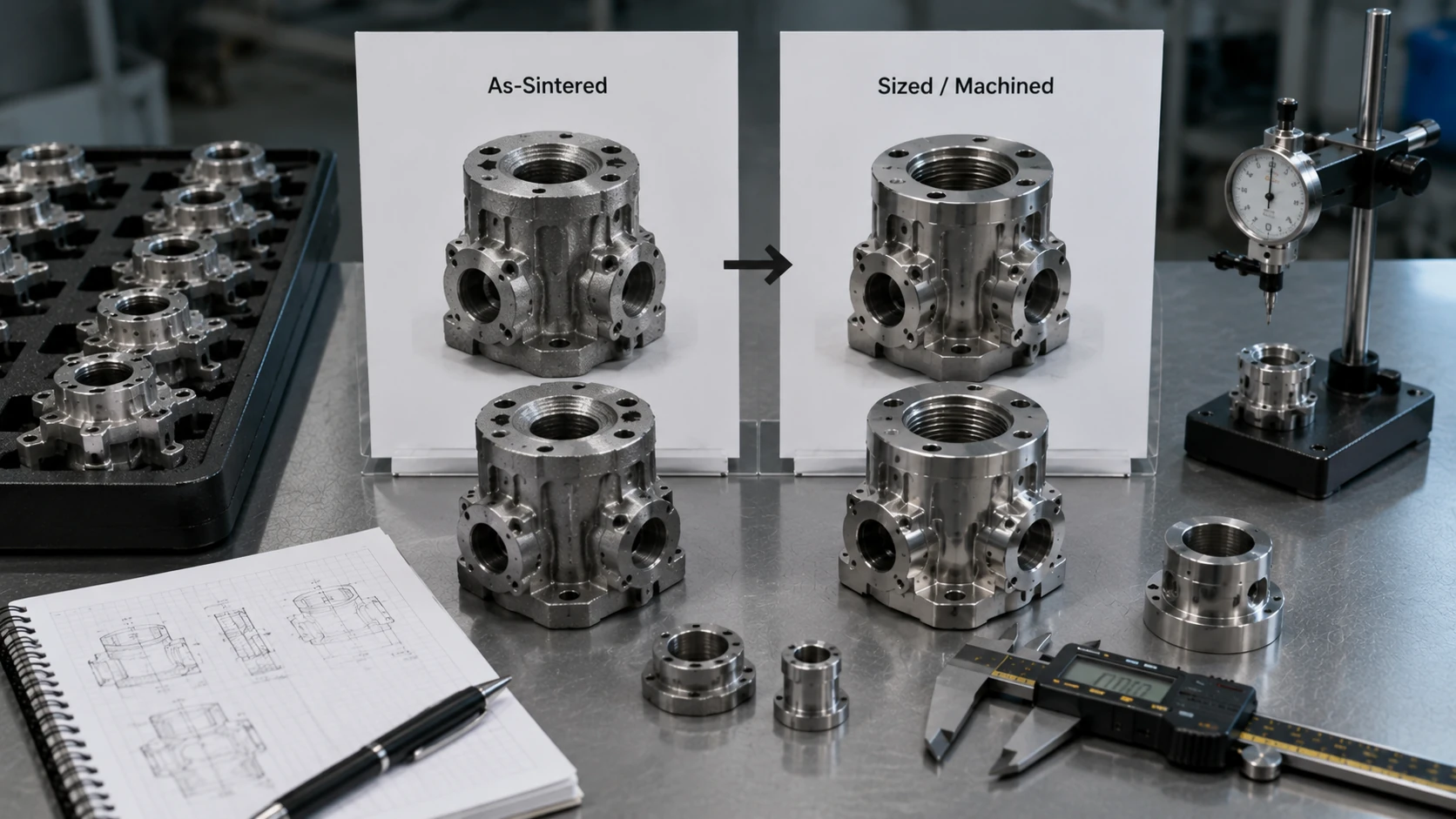
Control-route record: Record the selected candidate route for every critical characteristic, together with the required stock, tooling or process provisions and the evidence needed to confirm it.
Stage 5 · Define acceptance and inspection
How Should Critical Dimensions Be Measured and Accepted?
A tolerance becomes a usable manufacturing requirement only when the team agrees on the feature definition, applicable datum references, final inspection condition, and acceptance method. An accurate measurement cannot compensate for a manufacturing process that misses a requirement; equally, a satisfactory process cannot be assessed consistently without a defined measurement plan.
Functional Datums and Inspection References
Check whether the current drawing's datums correspond to the product's real assembly references. A surface used merely for holding a CNC blank may not exist or be suitable as a measurement datum on an MIM part. Do not silently change the design datum frame to suit the supplier's fixture: clarify the original intent and obtain design approval for any revised specification.
In an ISO GPS drawing, ISO 5459:2024 specifically addresses datum and datum-system specification, while ISO 1101:2017 addresses the notation and interpretation of geometrical tolerances. Do not treat a clamping pad, a CAD face name or a convenient CMM fixture as an approved replacement for the specified datum reference. If a former CNC reference surface is absent or unreliable after sintering, raise the mismatch to the design owner and document an approved measurement or drawing solution.
For F1, inspection may need to evaluate the hole's position relative to F2 or another approved datum reference frame. For F2, the team must establish which surface condition is acceptable for seating and orientation. Interpretation of geometric controls should follow the standard specified on the customer's drawing, such as ASME Y14.5-2018 (R2024) or an applicable ISO 1101-based GPS requirement. Those standards define specification language, not a blanket guarantee of MIM capability.
Inspection Methods and Acceptance Stages
Define the method according to the feature: CMM or another qualified dimensional method may be suitable for location, profile, or flatness; calibrated gauges can support repeat production checks; functional assembly tests may be needed for motion or fit; surface texture may require an agreed measurement method. For sealing or wear-critical interfaces, verification should address the relevant functional condition rather than relying only on one measured linear dimension.
For a narrow tolerance, measurement suitability is itself a technical decision. Confirm the instrument's calibration status and relevant measurement uncertainty, the accessibility and cleanliness of the feature, alignment to the required datum system, fixture stability and operator or program repeatability. NIST's dimensional-inspection planning research identifies uncertainty in measurement-equipment selection as an important source of manufacturing inspection risk. If the measurement method cannot reliably distinguish an acceptable feature from an unacceptable one, resolve the inspection plan before calling the process capable.
For F1, the final report should show the bore-size result and its location/orientation result under the approved datum scheme where specified. For F3, a motion or wear-related test may be required in addition to surface measurement, but a functional test does not silently replace a dimensional acceptance requirement. Keep developmental stage checks separate from the customer's final-finished-part acceptance condition, especially when downstream finishing can change the measured characteristic.
Specify when acceptance takes place: initial molding or sintering trials, after any sizing or machining, after specified heat treatment or surface finishing where applicable, and in released production. The customer and supplier should agree which characteristics need sample validation and which need routine production checks. Method suitability, access, fixture repeatability, and inspection frequency are project-specific.
| Feature | What to verify | Candidate method | When to check |
|---|---|---|---|
| F1 · Pin hole | Diameter and true positional relationship as specified | Appropriate bore measurement and qualified positional inspection | Trial and final condition; production plan by agreement |
| F2 · Locating face | Seating, flatness, and datum relationship | Qualified surface or CMM inspection, optionally functional fixture | After any corrective operation and at agreed acceptance stage |
| F3 · Sliding face | Contact geometry, finish, and movement where required | Surface evaluation plus appropriate functional test | Finished-part validation and agreed production checks |

Agree on the final acceptance condition
Specify whether a characteristic is accepted on an as-sintered, sized, machined, or final-finished part. Record the approved datum scheme, measurement method, and acceptance limits before sample inspection. A dimension that passed before finishing may need to be checked again if the later operation can alter it.
Inspection record: Link every critical characteristic to its approved datum, measurement method, acceptance condition, and validation stage. Transfer these items into the final drawing-review record.
Stage 6 · Document the decision
What Must Be Documented Before a CNC-to-MIM Tooling Review?
A CNC-to-MIM Critical Dimension Transfer Review Sheet records the approved drawing requirement, its functional purpose, the relevant MIM manufacturing risk, proposed control method, inspection plan, and outstanding approval for each characteristic. Customer engineering, supplier manufacturing, and quality can then resolve the same specific dimensional questions before quotations and tooling decisions are treated as technically settled.
Critical Dimension Transfer Review Sheet
Use the current approved 2D drawing, STEP 3D model, and available assembly information. Assign consistent feature IDs and copy the stated tolerances and GD&T controls without substitution. If a requirement or its approval is missing, mark it as unresolved; record who owns the clarification and what evidence is needed for the proposed manufacturing route.
Do not collapse independent requirements into a single pass/fail entry. For F1, the approved diameter tolerance and the separately specified positional relationship (if any) each need their own result, control route, evidence reference and open action. The table keeps the original F1 feature identity but separates those characteristic-level records as F1-D and F1-P. Retain customer drawing values verbatim; if an input is unavailable, enter not supplied rather than selecting an illustrative number that could be mistaken for an approved requirement.
| ID / feature | Original CNC requirement | Functional purpose | MIM risk to evaluate | Proposed route | Inspection / evidence | Status / owner |
|---|---|---|---|---|---|---|
| F1-D · Pin-hole size | Enter approved diameter and size tolerance; drawing revision | Specified pin fit or clearance | Final as-sintered bore size and any change during finishing | Evaluate as-sintered control; if needed, consider diameter-specific sizing or reaming subject to stock and geometry | Measure diameter in the agreed final condition; record actual trial values and method; currently E0 | Open · Design owner: requirement; supplier: size route and evidence |
| F1-P · Pin-hole position | Enter approved position/orientation control and datum references if specified | Pin alignment relative to approved assembly reference | Core-pin/tooling shift, distortion, or datum relationship after sintering | Evaluate tooling and support; datum-referenced location correction only if material and fixture conditions permit | Qualified position measurement to approved datums on final part; currently E0 pending drawing and trial results | Open · Design owner: datum intent; supplier + quality: route and measurement |
| F2 · Locating face | Enter approved flatness / relation to mating features | Assembly seating and orientation | Distortion and datum stability | Evaluate tooling/support and possible local correction | Final-condition datum and flatness inspection | Open · Engineering + quality |
| F3 · Sliding face | Enter dimension, finish, and any functional test requirement | Contact and motion | As-sintered surface condition and wear-contact behavior | Evaluate finished state and selective finishing | Surface measurement / assembly movement test | Open · Engineering + quality |
| G1 · Outer contour | Enter general profile and clearance requirements | Envelope / appearance, pending confirmation | Geometric consistency and any hidden clearance condition | Possible as-sintered route, subject to design approval | Approved envelope inspection if applicable | Clarify · Design owner |
Example only: no dimensions, tolerances, customer approvals, sampling results, or XTMIM production capability are asserted. Replace the explanatory cells with the actual drawing values and project evidence before use in a tooling decision.
F1 pin-hole review: separate size and location decisions
For this hypothetical F1/F2 assembly, the pin must fit the bore and align while the component seats on F2. The drawing's approved hole-size limit, position control, and datum references determine the two separate acceptance decisions. Actual drawing values and measurements are not available for this example.
- 1 · Record two distinct requirements
Copy F1's approved hole diameter and tolerance, then record its position requirement and datum reference to F2 if specified. Without those exact drawing values, both entries remain open.
- 2 · Test the candidate route against each
If hole size is the only issue and location already passes, suitable reaming might be assessed for diameter. If location fails, reaming alone is not the answer; investigate datum-referenced correction with available stock or upstream tooling/DFM changes.
- 3 · Ask for characteristic-specific evidence
Mark the starting record E0 (engineering hypothesis) unless supporting data exist. Request a supplier plan showing how the proposed final part will be measured for both diameter and true position using the approved datum scheme; update to E2 only after actual feature-level trial measurements are reviewed.
- 4 · Assign the gate and owner
Keep F1 Open — validation required. The design owner confirms the requirement, the supplier proposes and demonstrates the process route, and quality agrees on acceptance. Do not approve a size-only fix as proof that the location requirement is met.
F1 closure condition: keep F1-D and F1-P open until their approved requirements, final-condition measurement results, and process evidence have been reviewed separately. Identify the missing drawing callout or test result, the requested verification, and the person responsible for each open item.
A completed record should show the drawing revision, the drawing-characteristic identifier, approved acceptance criteria, proposed manufacturing stage, available measurement evidence, proposed next trial or inspection, responsible owner and closure decision. A status such as E2 / trial passed only describes the particular tested samples and conditions; it must not be written as proof of stable production performance without the corresponding repeatability evidence.
Assign decision authority on the record: the design owner confirms functional requirements and approves specification changes; the MIM supplier proposes the tooling and process route and supplies capability evidence; quality and customer engineering agree on the applicable inspection and acceptance requirements. Unverified control routes and disputed measurement methods remain open actions, not completed approvals.
Proceed, Revise, or Pause: The Review Decision
Use the completed sheet to decide whether the dimension review is ready to enter the broader feasibility and tooling-planning process. This is a review-gate decision—not approval to cut a mold.
Proceed to further evaluation
Functional requirements and datums are defined; a credible candidate route exists; unresolved capability questions have owners and a validation plan.
Revise and reassess
Some tolerances need design-owner review, an inspection definition is missing, or a geometry / process adjustment may close an identified gap.
Pause before tooling
A critical requirement has no viable or verifiable control route, a datum or acceptance condition remains disputed, or the proposed solution would undermine the conversion rationale.
What to send for an engineering review
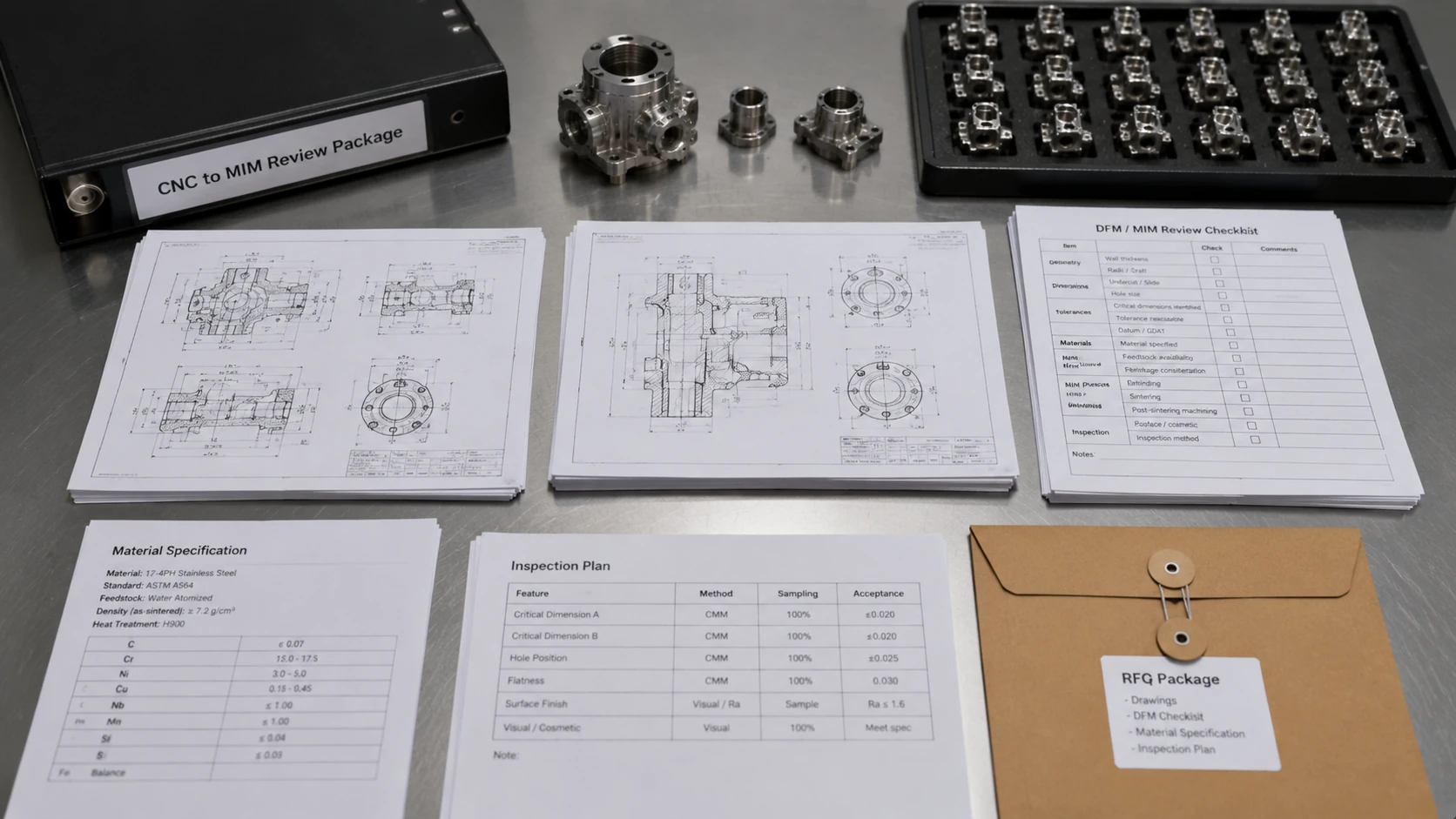
Provide the current 2D drawing with drawing revision, a STEP 3D model, material expectation, annual demand, critical feature IDs, mating or assembly information, required final surface condition, and inspection notes. Mark unapproved tolerance-change requests as open questions. The existing MIM tolerance and shrinkage checklist and RFQ preparation guide can help organize wider project inputs without replacing this feature-by-feature dimension review.
FAQ: CNC-to-MIM Dimensional Review Decisions
Several decisions depend on drawing details, the finished-part condition, or evidence that may not be available at the first supplier review.
If a molded hole meets its diameter tolerance, can it still fail the drawing?
Yes. A bore can satisfy its size tolerance while its position or orientation relative to an approved datum fails. Review the exact geometric control on the drawing and inspect size and location separately. Reaming does not normally correct the original hole alignment.
Can a CNC machining setup face become a different datum in MIM inspection?
Not automatically. A workholding surface is not necessarily the design datum. If the original CNC reference cannot be used on the finished MIM part, the customer design owner must approve any change to the specified datum scheme or acceptance definition. Record the agreed fixture and measurement approach.
Do passing first-article MIM samples prove production dimensional capability?
No. Part-specific samples show results for the tested route and condition only. Stable production claims need an agreed repeatability plan covering relevant characteristics and, where applicable, runs, cavities or lots. Record sample evidence separately from production evidence.
Should dimensions be checked before or after sizing, machining, or surface finishing?
Use intermediate measurements when they help diagnose or control the process, but define final acceptance at the drawing-specified part condition. If a secondary process may alter fit, position or surface function, recheck the affected characteristics after that operation and document the agreed method.
Can a non-contact CNC contour be relaxed for MIM?
It is a candidate for review, not an automatic relaxation. Confirm assembly envelope, fixture interfaces, clearance, handling, appearance and any downstream requirement first. Only the design owner can approve a revised drawing tolerance or profile requirement.