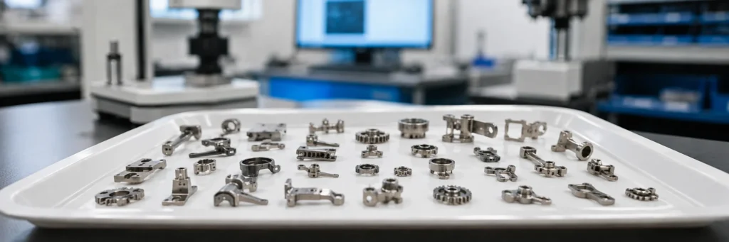
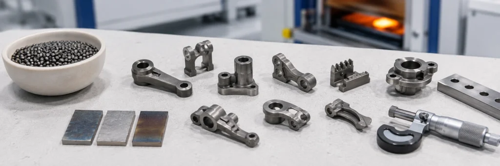
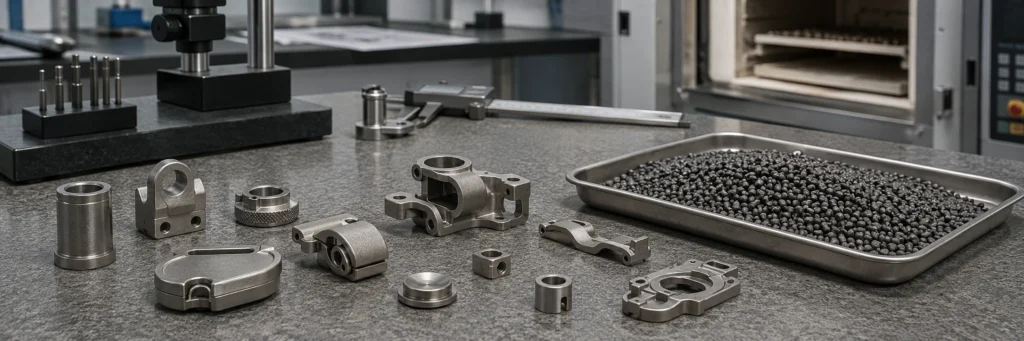
Early MIM or PM process selection should be reviewed before tooling assumptions are locked. For a new metal part, the practical question is usually not whether MIM is “better” than PM. The real question is whether the part should be designed around metal powder-binder feedstock injection molding or conventional press-and-sinter powder compaction before tooling assumptions …
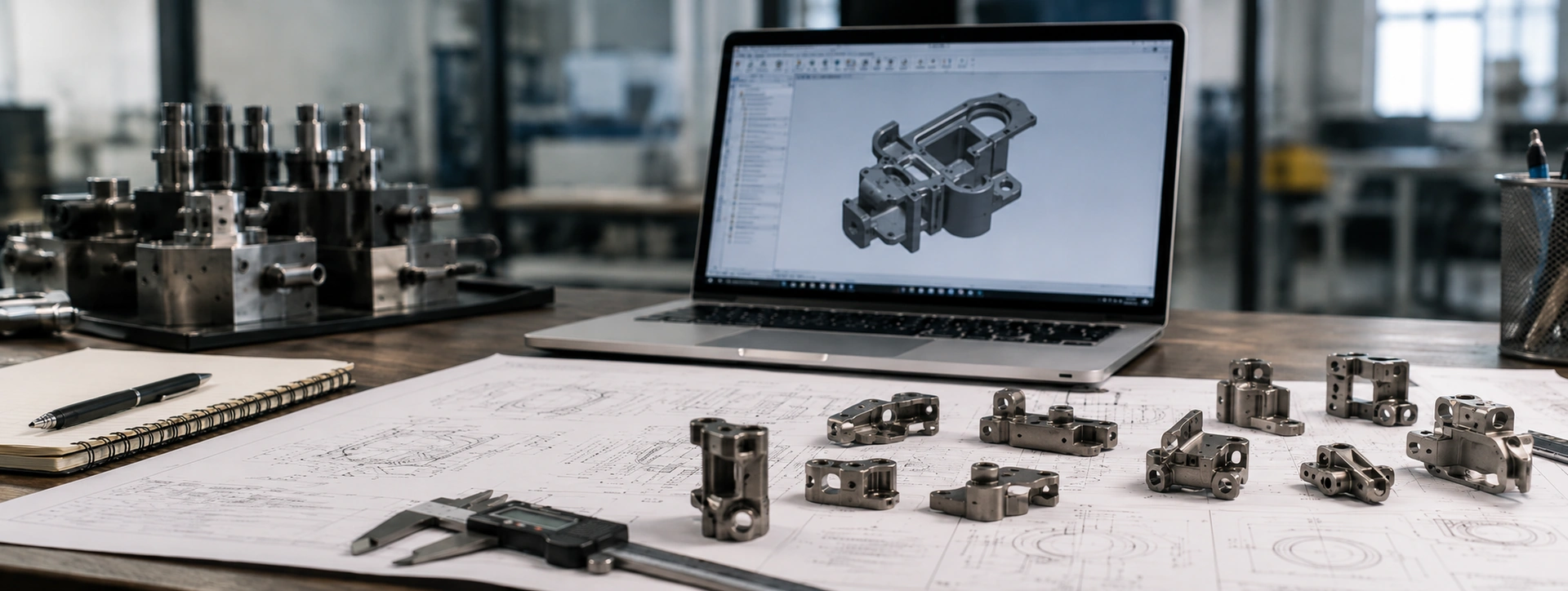
For a new metal part, the practical question is usually not whether MIM is “better” than PM. The real question is whether the part should be designed around metal powder-binder feedstock injection molding or conventional press-and-sinter powder compaction before tooling assumptions are locked. PM may be the better first review route when the geometry is pressable, ejectable, relatively regular, cost-sensitive, and can benefit from controlled porosity or oil-retaining function. MIM should be reviewed first when the part is small, complex, difficult to compact, or requires molded side features, thin walls, undercuts, higher density, or reduced secondary machining.
This early decision matters because the wrong route can affect tooling design, tolerance strategy, secondary operations, inspection planning, lead time, and total functional part cost. For a broader comparison of process capabilities and limitations, see the full MIM vs PM comparison. For a new-part review, keep the focus on geometry, function, tolerance priorities, porosity requirements, production volume, and secondary operations before RFQ or tooling.
Quick Answer: Choose MIM or PM Before Tooling Assumptions Are Locked
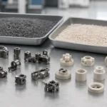
In practice, MIM and PM should be compared before the part design, tooling concept, tolerance plan, and RFQ assumptions become fixed. Both processes use metal powder and sintering, but their forming logic is different. Conventional PM forms a green compact by pressing powder in a rigid die, while MIM injects a metal powder-binder feedstock into a mold, followed by debinding and sintering.
A useful early review usually falls into three decisions:
| Early Decision | Usually Points Toward PM | Usually Points Toward MIM | Engineering Review Needed When |
|---|---|---|---|
| Geometry | The part is axial, regular, and easy to eject. | The part is small, complex, and three-dimensional. | Side features, undercuts, datum surfaces, or thin sections are uncertain. |
| Function | Controlled porosity, oil retention, or cost-sensitive structural function is acceptable. | Higher density, fine features, or integrated functions are required. | Density or porosity requirement is not clearly defined. |
| Cost Logic | The PM blank can meet most functional requirements with limited finishing. | MIM can reduce machining, assembly, or feature-by-feature processing. | Secondary operations dominate the cost comparison. |
| Project Stage | The design already follows PM compaction logic. | The design can still be optimized for MIM molding and sintering. | The drawing is not locked and both routes remain possible. |
The key is not to select a process only from the part name or material grade. A small gear, hinge, bracket, magnetic component, sleeve, or miniature structural part may be PM-friendly or MIM-friendly depending on its geometry, function, tolerance priorities, porosity requirement, and production plan.
Start with the Forming Route, Not the Alloy Name
A common RFQ mistake is to begin with the alloy name and ask, “Can this material be made by MIM or PM?” Material matters, but it is not the first selection filter. The first filter is the forming route.
MIM begins with fine metal powder mixed with binder to form feedstock. That feedstock must flow into a mold cavity, fill fine features, cool into a green part, survive handling, pass through debinding, and shrink during sintering in a controlled way. From a design review perspective, MIM evaluation focuses on molded geometry, wall thickness balance, gate location, debinding path, sintering support, shrinkage compensation, distortion risk, and final inspection. For more background on these steps, see the MIM process route.
PM begins with pressable powder, die filling, compaction, green compact strength, ejection, and sintering. PM review focuses on pressing direction, projected area, punch and core rod stability, ejection path, density distribution, sizing or coining needs, porosity, oil impregnation, and secondary machining.
The same alloy family may appear in both processes, but that does not mean the same drawing is equally suitable for both. A stainless steel part with a simple axial shape may be evaluated differently from a stainless steel part with side holes, deep slots, thin walls, and multiple functional datums.
The Metal Powder Industries Federation’s Metal Injection Molding Association (MIMA) evaluates MIM suitability through the combination of material performance, shape complexity, production quantity, and component cost rather than alloy name alone. Its Designing with MIM guidance discusses these factors in more detail.
Geometry First: Can the Part Be Pressed and Ejected Reliably?
Geometry is usually the most important early decision factor. If a part can be compacted, supported, ejected, sintered, and finished efficiently by conventional PM, PM may remain the better route. If the geometry fights the compaction direction or creates too much secondary machining, MIM may deserve earlier review.

Engineering takeaway:
For PM, start with axial compaction and clean ejection. For MIM, start with molded feature feasibility, gate strategy, debinding access, and sintering distortion risk.
For PM, the pressing direction defines what can be formed directly. Holes along the pressing direction can often be formed with core rods, but side holes, cross holes, transverse slots, external undercuts, and features that block ejection usually require machining, redesign, or more complex tooling. PickPM notes that core rods used for holes in the pressing direction must remain stable during compaction and ejection to avoid dimensional problems; its Design Considerations provides additional PM design guidance.
For MIM, the geometry window is wider, but not unlimited. Complex three-dimensional features still need mold release, gate design, balanced filling, debinding access, shrinkage control, and sintering support. MIMA notes that slides, cores, and other tooling elements can increase design complexity, but they may also add tooling and start-up engineering cost; see its complex MIM design guidance.
Geometry Review Checklist
| Geometry Question | Why It Matters | PM Review Point | MIM Review Point |
|---|---|---|---|
| Is the main shape axial and ejectable? | PM depends heavily on compaction and ejection. | Strong PM candidate if simple and stable. | MIM may not be needed unless other features justify it. |
| Are there side holes or cross holes? | They may require PM secondary machining. | Machining may increase cost and datum risk. | Molded features may be possible with tool action. |
| Are there undercuts or side grooves? | They can block ejection or require complex tooling. | Often difficult by basic press-and-sinter PM. | Possible in MIM with tool complexity and cost review. |
| Are thin or tall sections present? | They affect filling, strength, handling, and distortion. | May create density or green strength risk. | May create filling, debinding, or sintering distortion risk. |
| Are multiple features combined in one part? | Feature consolidation can change process economics. | PM may need several post-sinter operations. | MIM may consolidate features if tooling is justified. |
| Are critical datums related to hard-to-form features? | Inspection and machining references may become unstable. | Secondary machining may be needed. | Mold compensation and inspection plan must be reviewed. |
For the PM process itself, see the press-and-sinter powder metallurgy guide. For early MIM-or-PM selection, the most relevant PM factors are compaction direction, ejection, density and porosity, secondary operations, and finished-part cost.
When a New Part Should Be Reviewed as PM First
PM should often be reviewed first when the part geometry is relatively regular, the main features follow the pressing direction, and the functional requirements can be met with controlled density, controlled porosity, sizing, coining, oil impregnation, or limited secondary machining. PM is not a lower-grade route; for bushings, bearings, simple gears, sleeves, porous parts, and oil-impregnated components, it may be the correct engineering route rather than a compromise.

PM-first takeaway:
Regular axial geometry, controlled porosity, and cost-sensitive high-volume production may make conventional PM the more direct route. PM is not a lower-grade option when those conditions match the part function.
For many components, PM is the more direct engineering route. It can be efficient for bushings, bearings, simple gears, sleeves, spacers, porous parts, selected soft magnetic parts, and cost-sensitive high-volume structural components. MPIF describes conventional press-and-sinter PM as mixing powders with lubricants or additives, compacting the mixture in a die, and sintering the compact, with additives used to influence machinability, wear resistance, or lubricity. Its conventional PM overview explains the process in more detail.
PM-first review is usually reasonable when:
- The part can be pressed along a clear vertical axis.
- Side holes, side grooves, and undercuts are absent or not function-critical.
- The part can be ejected without damaging thin walls, flanges, or punches.
- The required density and porosity fit PM material design.
- Oil retention, self-lubrication, or porous function is useful.
- The production volume is stable and the design is cost-sensitive.
- Sizing, coining, or limited machining can control the key dimensions.
Typical PM-First Applications
| Part Type | Why PM May Fit | When MIM Review May Still Be Needed |
|---|---|---|
| Bushings and bearings | Controlled porosity and oil impregnation can support self-lubricating function. | Very small complex features, high-density requirement, or difficult side features. |
| Simple gears | Axial features and repeatable high-volume production can fit PM well. | Complex hubs, side holes, fine molded details, or tight datum relationships. |
| Spacers and sleeves | Regular geometry and straightforward ejection. | Thin side features, complex slots, or high-density requirements. |
| Porous components | Porosity may be part of the function. | If porosity is not acceptable or geometry becomes too complex. |
| Soft magnetic parts | PM may suit selected shapes and density strategies. | Very small complex geometries or special tolerance requirements. |
The important point is that PM should not be rejected just because MIM can achieve higher density or more complex shapes. If PM meets the functional requirement with lower process risk and fewer unnecessary operations, it may be the better choice.
When a New Part Should Be Reviewed as MIM First
MIM should be reviewed first when the part is small, complex, and difficult to produce efficiently by axial powder compaction. The strongest MIM candidates are usually parts where geometry, feature integration, or reduced secondary operations justify the extra process steps of molding, debinding, sintering, and shrinkage control.
MIM-first review is usually reasonable when:
- The part includes side features, undercuts, slots, fine teeth, small bosses, or internal details.
- The design would require multiple PM secondary machining operations.
- The part can consolidate several machined, stamped, or assembled pieces into one molded metal component.
- High density or lower porosity is important for strength, toughness, sealing, or functional loading.
- The part is small enough for MIM economics to be practical.
- The annual volume can support tooling and process development.
- The design is still flexible enough to optimize gate location, wall thickness, radii, and sintering support.
MIMA’s MIM design guidance explains that MIM allows part design freedom similar to plastic injection molding while producing a metal component, and that complexity can support the combining of multiple components or molding of functional features from the start. For broader MIM suitability beyond this PM comparison, see the MIM application selection guide.
MIM-First Design Indicators
| Design Indicator | Why It Favors MIM Review | What Still Needs Confirmation |
|---|---|---|
| Small complex 3D shape | Injection molding can form geometry not suitable for basic compaction. | Mold release, parting line, gate mark, and shrinkage. |
| Thin walls or fine features | MIM can mold small details if feedstock flow and handling are stable. | Filling balance, green strength, debinding path. |
| Side holes or undercuts | MIM tooling may form features that PM would machine later. | Tool complexity and cost. |
| Integrated functional details | MIM may reduce assembly or machining operations. | Whether added tooling cost is justified. |
| Higher density requirement | MIM often targets higher-density small parts. | Material, sintering cycle, and inspection method. |
| Multiple secondary operations in PM | MIM may reduce total process steps. | Total cost comparison and tolerance strategy. |
When MIM Should Not Be the First Choice
MIM should not be selected only because it can form complex metal parts. It may not be the first choice when the part is large and simple, the annual volume is too low to justify tooling, the geometry is already PM-friendly, the function requires controlled porosity or oil impregnation, or the drawing can be produced more directly by conventional PM with sizing, coining, or limited machining.
If the part still appears MIM-suitable, early DFM should review MIM wall thickness design, MIM gate design, and shrinkage compensation before tooling direction is confirmed.
Early Selection Matrix: PM First, MIM First, or Engineering Review Needed
Use the matrix below as an early screening tool. It does not replace drawing-level manufacturing review, but it can identify which route should be evaluated first and which questions must be resolved before tooling or RFQ.

How to use the matrix:
If the part has mixed geometry, unclear porosity requirements, tight datum chains, or uncertain annual volume, treat the result as preliminary and move to drawing-level engineering review before selecting a process.
| Review Factor | PM First | MIM First | Engineering Review Needed |
|---|---|---|---|
| Geometry | Regular, axial, easy to eject. | Small, complex, three-dimensional. | Mixed geometry or uncertain ejection path. |
| Side features | Few side features or acceptable machining. | Side holes, slots, undercuts, fine molded details. | Multiple side features tied to critical datums. |
| Density / porosity | Controlled porosity acceptable or useful. | Higher density or low porosity needed. | Function does not clearly define density requirement. |
| Cost logic | PM blank meets function with limited finishing. | Complexity may reduce machining or assembly. | Secondary operations dominate the comparison. |
| Volume | Stable high-volume simple part. | Stable medium/high-volume complex part. | Low, unstable, or prototype-only demand. |
| Tolerance | Sizing, coining, or limited machining can control key dimensions. | Shrinkage compensation and mold control are feasible. | Ultra-critical datum chain or uncertain inspection plan. |
| Material | Pressable powder route fits material and function. | MIM feedstock route fits material and fine geometry. | Material property target is unclear. |
| Best next step | PM supplier / process review. | MIM DFM review. | Submit drawing for process selection review. |
Engineering review trigger:
If two or more rows fall into “Engineering Review Needed,” submit the drawing before selecting PM tooling or MIM tooling. This is especially important when the part has side holes, undercuts, uncertain density or porosity requirements, multiple critical datums, or a production volume that has not been confirmed.
Density and Porosity: Is Porosity a Risk or Part of the Function?
Density should not be treated as a simple “higher is always better” comparison. In some projects, high density and low porosity are essential. In other projects, controlled porosity is part of the function.

Density / porosity note:
Density is a functional requirement, not a universal quality ranking. One part may require high density, while another may benefit from controlled PM porosity for lubrication, permeability, or density control.
MIM often targets higher-density small components where strength, toughness, corrosion performance, sealing, magnetic behavior, or fine functional features matter. EPMA notes that MIM uses fine powders and can reach high sintered densities, while also emphasizing that the process is mainly suited to complex shapes in higher quantities; if conventional pressing and sintering can produce the shape efficiently, MIM may not be economical. See the EPMA Metal Injection Moulding overview for additional process background.
PM may intentionally use porosity for oil retention, self-lubrication, filtration, sound damping, or controlled density. For bushings, bearings, porous components, and some friction or lubrication-related parts, porosity may be an engineering feature rather than a defect.
Density / Porosity Decision Table
| Requirement | PM May Be Better When | MIM May Be Better When |
|---|---|---|
| Oil-retaining function | Controlled interconnected porosity supports lubrication. | Oil retention is not the core function. |
| High strength in a small complex part | PM geometry or density may be limiting. | Higher density and molded complexity are needed. |
| Sealing or low leakage | Porosity may be a concern. | Lower porosity is important. |
| Porous or filter function | Porosity is intentionally designed. | MIM may not be appropriate. |
| Magnetic performance | PM may fit selected soft magnetic geometries. | MIM may be reviewed for small complex magnetic parts. |
| Structural loading | PM may work when density and geometry are suitable. | MIM may be reviewed when density and complex features matter together. |
Tolerance Strategy: Shrinkage Control vs Sizing and Coining
Tolerance comparison between MIM and PM should not be reduced to “which process is more precise.” The real question is where the dimensional risk comes from and how the process controls it.
In MIM, dimensional control depends on feedstock behavior, mold design, gate location, debinding stability, sintering shrinkage, part support, and inspection planning. The molded green part contains binder and shrinks during sintering, so tooling compensation and sintering control are central to the dimensional strategy. EPMA also notes that MIM differs from traditional PM because the green compact contains binder and large shrinkage occurs during sintering, making shrinkage control a major requirement.
In PM, dimensional control depends on powder filling, compaction uniformity, green strength, ejection, sintering change, die wear, and secondary operations such as sizing, coining, repressing, or machining. PM can be efficient when key dimensions are aligned with the process window, but complex datum relationships may create additional inspection and finishing risk.
For MIM-specific dimension planning, see the MIM tolerances page.
Tolerance Review Questions Before Process Selection
| Question | Why It Matters |
|---|---|
| Which dimensions are truly critical to function? | Not every dimension needs the same tolerance strategy. |
| Are critical datums located on molded, pressed, or machined surfaces? | Datum choice affects inspection stability. |
| Does the feature depend on side machining after PM sintering? | Secondary operations may change cost and accuracy. |
| Can MIM shrinkage be compensated through tooling and support? | Complex shapes may need DFM changes before tooling. |
| Are flatness, concentricity, or positional tolerances driving the process choice? | These often matter more than basic size tolerance. |
| Is inspection based on part function or only drawing defaults? | Over-tight drawing defaults can create unnecessary cost. |
Cost Logic: Compare Functional Part Cost, Not Only Unit Price
For new metal parts, cost comparison should be based on the finished functional part, not only the formed blank.
PM can be more economical when the compacted and sintered part already satisfies most of the function with limited secondary processing. The tooling and production logic can be efficient for relatively regular, high-volume, cost-sensitive parts.
MIM may be justified when the geometry is complex enough to reduce machining, assembly, welding, or multiple feature-specific operations. MIMA’s complex design guidance notes that added features in MIM can have economic benefits by eliminating secondary processes or assembly operations, but they typically add tooling and start-up engineering cost.
For a broader cost breakdown, see the metal injection molding cost guide. In an early MIM-or-PM review, cost should be compared at the finished-part level, including tooling, secondary machining, sizing or coining, assembly, inspection, and expected production volume.
Functional Cost Review Table
| Cost Factor | PM Cost Question | MIM Cost Question |
|---|---|---|
| Tooling | Can the die, punches, and core rods form the part reliably? | Does the mold need slides, cores, complex gating, or special support? |
| Powder / feedstock | Is the powder system suitable for compaction and target density? | Does the feedstock support flow, debinding, and sintering requirements? |
| Secondary operations | Are machining, sizing, coining, or oil impregnation expected and controlled? | Can molded features reduce machining or assembly? |
| Tolerance | Can PM hold or finish the critical dimensions efficiently? | Can shrinkage compensation and inspection control the critical dimensions? |
| Volume | Is the volume stable enough for PM tooling efficiency? | Is the volume high enough to amortize MIM tooling and development? |
| Quality risk | Are density, ejection, or porosity risks controlled? | Are molding, debinding, distortion, or gate mark risks controlled? |
| Total function | Does the finished part meet the application with minimal extra work? | Does MIM reduce total manufacturing complexity? |
Common Early-Stage Mistakes When Comparing MIM and PM
Mistake 1: Choosing by Material Name Before Reviewing Geometry
Material selection is important, but geometry controls the forming route. A part made from stainless steel, low-alloy steel, or soft magnetic material may still be unsuitable for one route if the shape cannot be compacted, ejected, molded, debound, or sintered reliably.
Mistake 2: Assuming MIM Is an Upgrade from PM
MIM is not a universal upgrade. PM may be the better process when the part is pressable, cost-sensitive, high-volume, and can benefit from controlled porosity or straightforward secondary finishing.
Mistake 3: Assuming PM Is Always Cheaper
PM is often economical for simple pressable parts, but it may lose cost advantage if the part requires multiple side holes, tight machined datums, complex finishing, or repeated design compromise. Cost must be reviewed at the finished-part level.
Mistake 4: Ignoring Functional Porosity
Porosity can be a risk in one part and a functional feature in another. A sealed high-strength component may favor MIM review, while an oil-impregnated bearing may favor PM.
Mistake 5: Reviewing Process Selection After Tooling Is Already Fixed
Once tooling direction is locked, design changes become slower and more expensive. Early process selection should happen before finalizing parting logic, pressing direction, gate location, datum scheme, and critical tolerance assumptions.
Representative Scenario: A Side-Hole Component Initially Reviewed as PM
A small metal component looked simple in the front view, so a PM route initially appeared reasonable. Drawing review then showed several side holes and a functional slot tied to assembly datums. Because the early discussion had focused mainly on material and projected annual volume, the effect of forming direction on machining, inspection, and datum control had not been fully considered.
PM itself was not the problem; the geometry was a poor match for straightforward press-and-sinter forming. The cost driver shifted from the PM blank to secondary machining and datum control. The part was therefore reviewed as a possible MIM candidate by comparing PM blank cost plus side machining with MIM tooling, molded-feature feasibility, gate location, wall-thickness balance, sintering support, and final inspection.
For similar parts, review pressing direction, side features, datum relationships, and the secondary-machining load before assuming PM will deliver the lowest finished-part cost.
Representative Scenario: A Bushing Design That Should Stay PM-First
A small sleeve-like part was considered for MIM because it used metal powder and required repeatable production. The initial assumption was that higher density would automatically improve the component.
In this case, the part function depended on controlled porosity and oil-retaining behavior, while the geometry was regular, axial, and well suited to compaction and ejection. Keeping the project PM-first allowed the review to focus on powder selection, density target, porosity control, oil impregnation, sizing requirements, and inspection of the functional dimensions.
The practical decision is not whether higher density is generally better. First determine whether porosity is a defect, a neutral characteristic, or part of the intended function.
What to Send for an Early MIM or PM Process Review
A useful process recommendation requires more than a part name. The review should be based on drawing geometry, function, tolerance priorities, material requirements, density or porosity expectations, production volume, and secondary operations.

What the review needs:
A part name or alloy grade is not enough for process selection. The review also needs geometry, tolerances, datums, density or porosity requirements, production volume, and expected secondary operations.
Process Review Input Checklist
| Information to Provide | Why It Matters |
|---|---|
| 2D drawing with dimensions and tolerances | Shows critical features, datums, tolerance priorities, and inspection requirements. |
| 3D CAD file | Helps review parting direction, undercuts, wall thickness, slots, bosses, and molded or compacted geometry. |
| Material grade or target properties | Supports material suitability review for MIM feedstock or PM powder route. |
| Annual volume and project stage | Determines whether tooling and process development can be justified. |
| Critical dimensions and functional datums | Identifies which features drive process risk and inspection planning. |
| Density, porosity, or oil-retention requirement | Helps decide whether PM porosity is useful or MIM density is needed. |
| Surface finish and appearance requirements | Affects gate mark, parting line, machining, polishing, or finishing review. |
| Heat treatment or magnetic requirements | May affect material selection and final property validation. |
| Current manufacturing concern | Helps compare MIM, PM, CNC, casting, stamping, or other routes if relevant. |
| Secondary operations expected | Shows whether machining, sizing, coining, plating, polishing, or assembly changes process economics. |
For projects close to quotation, the RFQ preparation guide can help organize drawing, material, tolerance, surface finish, volume, inspection, and application information before contacting a supplier.
Request an Early MIM or PM Process Review
If your new metal part has side holes, undercuts, thin walls, complex three-dimensional features, density or porosity requirements, tight datum relationships, or uncertain production volume, submit the drawing for early process review before tooling assumptions are locked.
Please provide 2D drawings, 3D CAD files if available, material requirements, annual volume, critical dimensions, density or porosity needs, surface finish requirements, heat treatment requirements, and any current manufacturing concerns. XTMIM can review whether the part should be evaluated as PM-first, MIM-first, or engineering-review-needed before RFQ details are finalized.
Reviewed by XTMIM Engineering Team
Early MIM-versus-PM review should cover process suitability, part geometry, PM compaction and ejection limits, MIM molding feasibility, debinding and sintering shrinkage risk, material selection, density and porosity requirements, tolerance strategy, secondary operations, inspection requirements, and RFQ input quality.
Final process selection should be confirmed through drawing-level review, material requirements, tolerance priorities, application conditions, annual volume, tooling feasibility, and supplier-specific manufacturing assessment.
Technical References and Standards
Technical references and industry association materials can support early MIM and PM discussions, but they should not replace drawing-level DFM review. Useful background references for this topic include EPMA materials on metal injection moulding, MIMA design guidance for MIM, PickPM design considerations for PM, and MPIF information on conventional powder metallurgy.
Final material acceptance, mechanical properties, density targets, porosity limits, tolerances, and inspection methods should be confirmed against the applicable customer drawing, purchase specification, material standard, MPIF / ASTM / ISO requirements where relevant, and project-specific quality plan.
FAQ: MIM or PM for New Metal Parts
Should a new metal part be designed for MIM or PM first?
Start with geometry and function. If the part is axial, regular, pressable, ejectable, cost-sensitive, and can use controlled porosity, PM may be the better first review route. If the part is small, complex, three-dimensional, difficult to compact, or requires higher density with molded fine features, MIM should be reviewed first.
Is MIM better than PM for complex metal parts?
MIM is often better for small complex metal parts with side features, undercuts, thin walls, fine details, or integrated functions. However, MIM is not automatically better for every powder metal component. If the shape can be produced efficiently by conventional pressing and sintering, PM may remain more practical.
When is PM a better choice than MIM?
PM is often better when the part has a regular pressable shape, clear ejection path, stable high-volume demand, cost-sensitive requirements, and functional use for controlled porosity or oil impregnation. Common examples include bushings, bearings, sleeves, simple gears, spacers, and selected porous or structural parts.
When should MIM not be used instead of PM?
MIM should not be used only because it can make metal parts. It may not be the first choice when the part is large and simple, the volume is too low for tooling, the design already fits PM compaction, or the function requires controlled porosity or oil impregnation. In those cases, PM review should remain the first route.
Does higher density always mean MIM is the better process?
No. Higher density can be important for strength, toughness, sealing, or certain precision functions, but some PM parts intentionally use porosity for lubrication, permeability, or density control. The correct choice depends on the part function, not density alone.
Is PM always cheaper than MIM?
PM is often more economical for simple, pressable, high-volume parts. MIM may become more cost-effective when complex geometry reduces machining, assembly, welding, or multiple secondary operations. Compare the finished functional part cost, not only the formed blank price.
What information is needed for a MIM or PM process review?
Send a 2D drawing, 3D CAD file if available, material requirement, annual volume, critical dimensions, tolerance notes, density or porosity requirement, surface finish, heat treatment needs, application environment, and expected secondary operations.
Can one drawing be reviewed for both MIM and PM?
Yes. A useful early review should compare forming feasibility, pressing direction, ejection, molded feature risk, density or porosity needs, tolerance strategy, secondary operations, material suitability, and production volume before recommending MIM, PM, or another manufacturing route.